Suzuki Grand Vitara JB627. Manual — part 27

1A-57 Engine General Information and Diagnosis:
Excessive hydrocarbon
(HC) emission or carbon
monoxide (CO)
Engine not at normal operating
temperature
Clogged air cleaner
Refer to “Air Cleaner Filter Inspection and
Cleaning in Section 1D”.
Vacuum leaks
Refer to “Engine Vacuum Check in Section
1D”.
Faulty spark plug
Refer to “Spark Plug Inspection in Section 1H”.
Faulty ignition coil with ignitor
Refer to “Ignition Coil Assembly (Igniter and
Ignition Coil) Inspection in Section 1H”.
Low compression
Refer to “Compression Check in Section 1D”.
Lead contamination of three way
catalytic converter
Check for absence of filler neck restrictor.
Faulty evaporative emission control
system
Refer to “EVAP Canister Purge Valve and Its
Circuit Inspection in Section 1B”.
Fuel pressure out of specification
– Dirty fuel filter
– Dirty or clogged fuel hose or pipe
– Faulty fuel pressure regulator
– Faulty fuel pump
Refer to “Fuel Pressure Check”.
Closed loop system (A/F feedback
compensation) fails (faulty TP sensor,
poor performance of ECT sensor or
MAF sensor)
Refer to “Electric Throttle Body Assembly On-
Vehicle Inspection in Section 1C”, “Engine
Coolant Temperature (ECT) Sensor Inspection
in Section 1C” or “Mass Air Flow (MAF) and
Intake Air Temperature (IAT) Sensor On-
Vehicle Inspection in Section 1C”.
Faulty electric throttle body assembly
Refer to “Electric Throttle Body Assembly On-
Vehicle Inspection in Section 1C”.
Faulty accelerator pedal position (APP)
sensor assembly
Refer to “Accelerator Pedal Position (APP)
Sensor Assembly Inspection in Section 1C”.
Faulty injector
Refer to “Fuel Injector Circuit Check”.
Faulty ECM
Refer to “Inspection of ECM and Its Circuits”.
Excessive nitrogen
oxides (NOx) emission
Improper ignition timing
Refer to “Ignition Timing Inspection in Section
1H”.
Lead contamination of catalytic
converter
Check for absence of filler neck restrictor.
Faulty EGR system (if equipped)
Refer to “EGR System Inspection (If Equipped)
in Section 1B”.
Fuel pressure out of specification
– Dirty fuel filter
– Dirty or clogged fuel hose or pipe
– Faulty fuel pressure regulator
– Faulty fuel pump
Refer to “Fuel Pressure Check”.
Closed loop system (A/F feedback
compensation) fails (faulty TP sensor,
poor performance of ECT sensor or
MAF sensor)
Refer to “Electric Throttle Body Assembly On-
Vehicle Inspection in Section 1C”, “Engine
Coolant Temperature (ECT) Sensor Inspection
in Section 1C” or “Mass Air Flow (MAF) and
Intake Air Temperature (IAT) Sensor On-
Vehicle Inspection in Section 1C”.
Faulty electric throttle body assembly
Refer to “Electric Throttle Body Assembly On-
Vehicle Inspection in Section 1C”.
Faulty accelerator pedal position (APP)
sensor assembly
Refer to “Accelerator Pedal Position (APP)
Sensor Assembly Inspection in Section 1C”.
Faulty injector
Refer to “Fuel Injector Circuit Check”.
Faulty ECM
Refer to “Inspection of ECM and Its Circuits”.
Condition
Possible cause
Correction / Reference Item
Engine General Information and Diagnosis: 1A-58
Malfunction Indicator Lamp Does Not Come ON with Ignition Switch ON and Engine Stop (but
Engine Can Be Started)
S6JB0B1104012
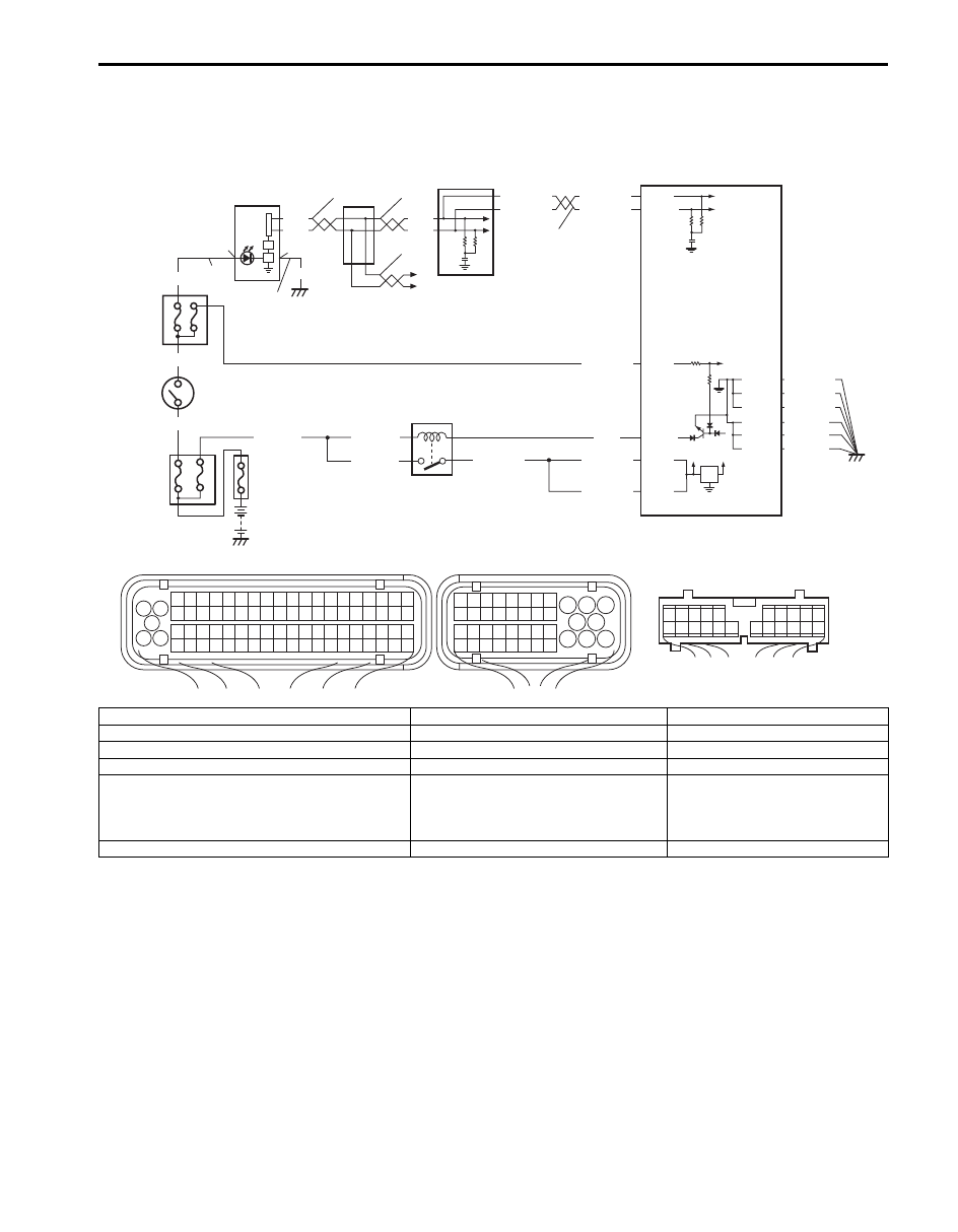
Wiring Diagram
Circuit Description
When the ignition switch is turned ON, ECM causes the main relay to turn ON (close the contact point). Then, ECM
being supplied with the main power, transmits indication ON signal of malfunction indicator lamp (MIL) to combination
meter in order to turn MIL ON. And then, combination meter turns MIL ON. When the engine starts to run and no
malfunction is detected in the system, ECM transmits MIL indication OFF signal to combination meter in order to turn
MIL OFF. And then, combination meter turns MIL OFF, but if a malfunction was or is detected, MIL remains ON even
when the engine is running.
BLK/WHT
BLU/BLK
BLU/BLK
BLU/BLK
WHT/GRN
BLK/RED
BLK/RED
BLK/RED
BLK/YEL
BLU
12V
5V
2
3
8
6
5
7
WHT/RED
WHT/BLU
WHT/RED
WHT/BLU
E23-8
E23-9
E23-2
E23-16
E23-17
E23-3
10
12
11
1
PPL/RED
C37-73
C37-39
C37-58
BLK/ORN
C37-59
C37-80 BLK/ORN
C37-81 BLK/ORN
BLK/YEL
BLK/YEL
BLK/YEL
4
WHT
RED
WHT
RED
BLK
9
13
12
12
12
1
3 2
4
5
6
7
8
9
1110
12
13
14
15
16
17
18
19
20
17
18
19
20
21
22
23
24
25
26
27
28
29
30
31
33
34
35
36
37
38
39
40
32
1
2
3
4
5
6
7
8
9
10
11
12
13
14
15
16
21
22
23
24
25
26
27
28
29
30
31
32
33
34
35
36
37
38
39
40
41
42
43
44
45
46
47
48
49
50
51
52
53
54
55
56
57
58
59
60
61
62
63
64
65
66
67
68
69
70
71
72
73
74
75
76
77
78
79
80
81
1
2
3
4
5
6
7
8
9
10
11
17
1615141312
2221201918
G28
[B]
G28-15
G
G28-13
P
[A]
C37
E23
I6JB01110026-02
[A]: ECM connector (viewed from harness side)
3. Main relay
9. ABS or ESP
® control module
[B]: Combination meter connector (viewed from harness side)
4. Malfunction indicator lamp in combination meter 10. “FI” fuse
P: Combination meter power supply circuit
5. “IG COIL” fuse
11. “IGN” fuse
G: Combination meter ground circuit
6. “METER” fuse
12. CAN communication line
1. Fuse box No.2
7. ECM
13. To other control module TCM (A/T
model), BCM, 4WD control module (if
equipped), keyless start control module
(if equipped) and steering angle sensor
(ESP
® model)
2. Ignition switch
8. Junction block

1A-59 Engine General Information and Diagnosis:
Troubleshooting
NOTE
• Before performed troubleshooting, be sure to read the “Precautions of ECM Circuit Inspection”.
• When measuring circuit voltage, resistance and/or pulse signal at ECM connector, connect the
special tool to ECM and/or the ECM connectors referring to “Inspection of ECM and Its Circuits”.
Step
Action
Yes
No
1
MIL power supply check
1) Turn ignition switch to ON position.
Do other warning lights come ON?
Go to Step 2.
Go to Step 4.
2
DTC check
1) Connect scan tool to DLC with ignition switch turned
OFF.
2) Turn ON ignition switch and check DTC.
Is there DTC(s) U0073 and/or U0121?
Go to applicable DTC
diag. flow.
Go to Step 3.
3
DTC check in ABS or ESP
® control module
1) Check DTC in ABS or ESP
® control module.
Is there DTC(s) U1073 and/or U1100?
Go to applicable DTC
diag. flow.
Substitute a known
good combination meter
and recheck. If MIL still
remains OFF, substitute
a known good ECM and
recheck.
4
Combination meter power supply and ground circuit
check
1) Turn ignition switch OFF position.
2) Disconnect connector from combination meter.
3) Check for proper connection to power supply and
ground terminals of combination meter connector.
4) If connections are OK, check that combination meter
circuit is as follows.
• Circuit voltage between combination meter power
supply terminal and vehicle body ground is 10 – 14 V.
• Wiring harness resistance of combination meter
ground terminal and vehicle body ground is less than
3
Ω.
Are they in good condition?
Go to Step 5.
Repair or replace.
5
CAN communication line circuit check
1) Check CAN communication circuit between control
modules for open, short, high resistance and
connections referring to Step 3 of “DTC U0073: Control
Module Communication Bus Off”
Is circuit in good condition?
Substitute a known
good combination meter
and recheck. If MIL still
remains OFF, substitute
a known good ECM and
recheck.
Repair or replace.
Engine General Information and Diagnosis: 1A-60
Malfunction Indicator Lamp Remains ON after Engine Starts
S6JB0B1104013
Wiring Diagram and Circuit Description
Refer to “Malfunction Indicator Lamp Does Not Come ON with Ignition Switch ON and Engine Stop (but Engine Can
Be Started)”.
Troubleshooting
NOTE
• Before performed troubleshooting, be sure to read the “Precautions of ECM Circuit Inspection”.
• When measuring circuit voltage, resistance and/or pulse signal at ECM connector, connect the
special tool to ECM and/or the ECM connectors referring to “Inspection of ECM and Its Circuits”.
Step
Action
Yes
No
1
DTC check
1) Start engine and recheck DTC of ECM and TCM (A/T
model) while engine running.
Is there any DTC(s)?
Go to Step 2 of “Engine
and Emission Control
System Check”, Step 2
of “A/T System Check in
Section 5A”.
Go to Step 2.
2
CAN communication line circuit check
1) Check CAN communication line circuit between control
modules for open, short, high resistance and
connections referring to Step 9 to 14 “DTC U0073:
Control Module Communication Bus Off”.
Is circuit in good condition?
Substitute a known
good combination meter
and recheck. If MIL still
remains ON, substitute
a known good ECM and
recheck.
Repair or replace CAN
communication circuit.
Нет комментариевНе стесняйтесь поделиться с нами вашим ценным мнением.
Текст