Suzuki Grand Vitara JB627. Manual — part 110
1H-2 Ignition System:
Schematic and Routing Diagram
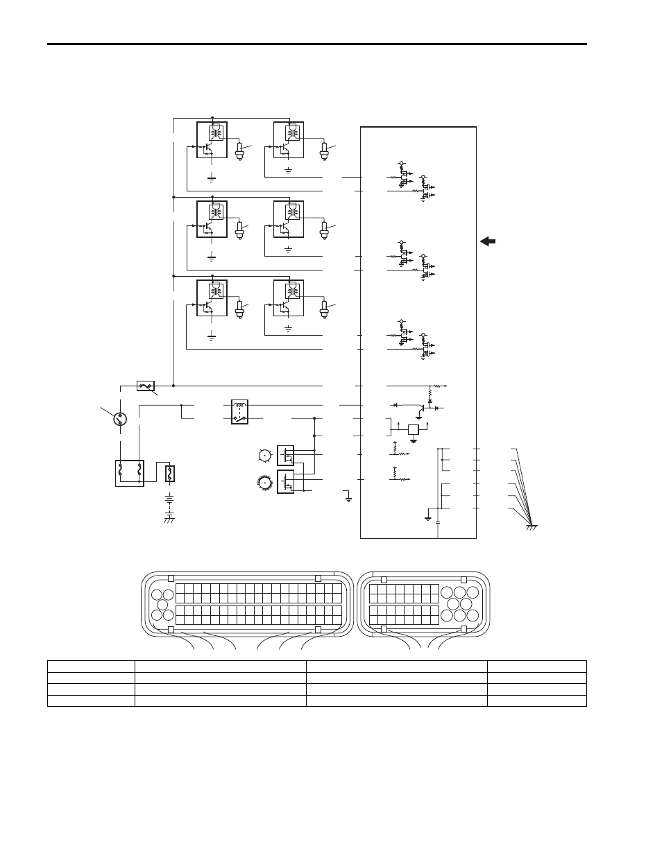
Ignition System Wiring Circuit Diagram
S6JB0B1802001
E23-16
E23-8
12V
5V
E23-2
E23-3
BLK/WHT
BLU/BLK
BLU/BLK
BLU/BLK
BLK/RED
BLK/RED
BLK/RED
BLK/YEL
WHT/GRN
BLU
1
13
14
15
2
5V
WHT/RED
BLK/WHT
BRN/BLK
BRN
C37-76
C37-57
BLK/WHT
BRN/YEL
BRN/WHT
C37-75
C37-56
BLK/ORN
BLK/ORN
BLK/ORN
BLK/ORN
BLK/YEL
BLK/YEL
BLK/YEL
C37-47
10
10
10
10
6
8
7
9
3
BLK
BLK/ORN
C37-59
C37-58
C37-39
C37-80
C37-81
C37-73
BLK/ORN
BLK/ORN
WHT/BLU
C37-66
BLK/YEL
4
5
BLK/YEL
BLK/WHT
C37-55
BLK/ORN
BLK/ORN
10
10
12
PPL/RED
BRN/RED
C37-74
11
1
3 2
4
5
6
7
8
9
1110
12
13
14
15
16
17
18
19
20
17
18
19
20
21
22
23
24
25
26
27
28
29
30
31
33
34
35
36
37
38
39
40
32
1
2
3
4
5
6
7
8
9
10
11
12
13
14
15
16
21
22
23
24
25
26
27
28
29
30
31
32
33
34
35
36
37
38
39
40
41
42
43
44
45
46
47
48
49
50
51
52
53
54
55
56
57
58
59
60
61
62
63
64
65
66
67
68
69
70
71
72
73
74
75
76
77
78
79
80
81
I6JB01180001-01
1. Ignition switch
5. CKP sensor
9. Ignition coil assembly (For No.4 cylinder)
13. Main relay
2. “IG COIL” fuse
6. Ignition coil assembly (For No.1 cylinder)
10. Spark plug
14. Sensed information
3. ECM
7. Ignition coil assembly (For No.2 cylinder)
11. Ignition coil assembly (For No.5 cylinder)
15. Junction block
4. CMP sensor
8. Ignition coil assembly (For No.3 cylinder)
12. Ignition coil assembly (For No.6 cylinder)
Ignition System: 1H-3
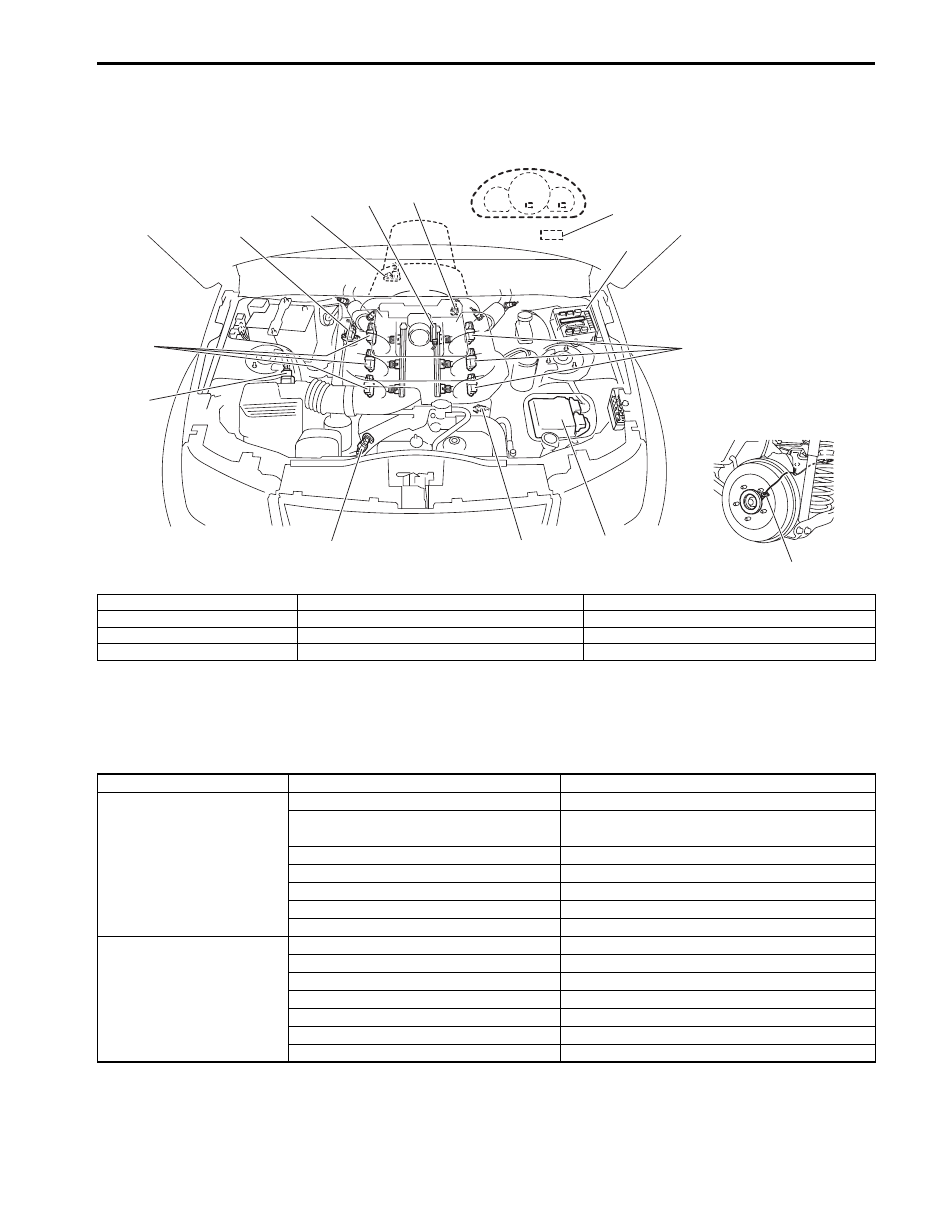
Component Location
Ignition System Components Location
S6JB0B1803001
Diagnostic Information and Procedures
Ignition System Symptom Diagnosis
S6JB0B1804001
12
12
6
2
1
3
4
5
7
8
9
11
10
I6JB01180002-01
1. ECM
5. ECT sensor
9. Data link connector
2. CMP sensor
6. MAF and IAT sensor
10. Rear wheel sensor (RH, LH) (VSS)
3. CKP sensor
7. Electric throttle body assembly
11. Fuse box No.2
4. MAP sensor (if equipped)
8. Knock sensor
12. Ignition coil assembly
Condition
Possible cause
Correction / Reference Item
Engine cranks, but will
not start or hard to start
(No spark)
Blown fuse for ignition coil assembly
Replace.
Loose connection or disconnection of
lead wire
Connect securely.
Faulty spark plug(s)
Replace.
Faulty ignition coil assembly(s)
Replace.
Faulty CMP sensor or sensor rotor
Clean, tighten or replace.
Faulty CKP sensor or sensor plate
Clean, tighten or replace.
Faulty ECM
Replace.
Poor fuel economy or
engine performance
Incorrect ignition timing
Check related sensors and CKP sensor plate.
Faulty spark plug(s)
Replace.
Faulty ignition coil assembly(s)
Replace.
Faulty CMP sensor or sensor rotor
Clean, tighten or replace.
Faulty CKP sensor or sensor plate
Clean, tighten or replace.
Faulty ECM
Replace.
Faulty knock sensor
Replace.

1H-4 Ignition System:
Ignition System Check
S6JB0B1804002
Step
Action
Yes
No
1
Was “Engine and Emission Control System Check”
performed?
Go to Step 2.
Go to “Engine and
Emission Control
System Check in
Section 1A”.
2
Ignition spark test
1) Check all spark plugs for condition and type referring to
2) If OK, perform ignition spark test referring to “Ignition
Is spark emitted from all spark plugs?
Go to Step 11.
Go to Step 3.
3
DTC check
1) Perform DTC check referring to “DTC Check in Section
1A”.
Is DTC stored in ECM?
Go to applicable DTC
diag. flow.
Go to Step 4.
4
Electrical connection check
1) Check ignition coil assemblies for electrical connection.
Are they connected securely?
Go to Step 5.
Connect securely.
5
Ignition coil assembly power supply and ground circuit
check
1) Check ignition coil assembly power supply and ground
circuits for open and short.
Are circuits in good condition?
Go to Step 6.
Repair or replace.
6
Ignition coil assembly check
1) Check ignition coil for resistance referring to “Ignition
Coil Assembly (Igniter and Ignition Coil) Inspection”.
Is check result satisfactory?
Go to Step 7.
Replace ignition coil
assembly.
7
CKP sensor check
1) Check CKP sensor referring to “Camshaft Position
(CMP) Sensor and Crankshaft Position (CKP) Sensor
Inspection in Section 1C”.
Is check result satisfactory?
Go to Step 8.
Tighten CKP sensor
bolt, replace CKP
sensor or CKP sensor
plate.
8
CMP sensor check
1) Check CMP sensor referring to “Camshaft Position
(CMP) Sensor and Crankshaft Position (CKP) Sensor
Inspection in Section 1C”.
Is check result satisfactory?
Go to Step 9.
Tighten CMP sensor
bolt, replace CMP
sensor or intake
camshaft.
9
Ignition trigger signal circuit check
1) Check ignition trigger signal wire for open, short and
poor connection.
Is circuit in good condition?
Go to Step 10.
Repair or replace.
10 A known-good ignition coil assembly substitution
1) Substitute a known-good ignition coil assembly and then
repeat Step 2.
Is check result of Step 2 satisfactory?
Go to Step 11.
Substitute a known-
good ECM and then
repeat Step 2.
Ignition System: 1H-5
Reference
Refer to “Reference waveform No.17 to 20” and “Reference waveform No.24 to 26” under “Inspection of ECM and Its
Circuits in Section 1A” for waveform of ignition trigger signal.
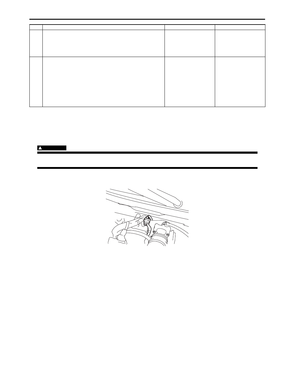
Ignition Spark Check
S6JB0B1804003
WARNING
!
Without disconnection of injector coupler, combustible gas may come out from spark plug holes
during this test and may get ignited in engine room.
1) Remove surge tank cover.
2) Disconnect injector coupler (1).
3) Remove spark plug and check it for condition and type, referring to “Spark Plug Inspection”.
4) If OK, connect ignition coil coupler to ignition coil assembly and connect spark plug to ignition coil assembly.
Ground spark plug.
5) Crank engine and check if each spark plug sparks.
If no spark is emitted, inspect the related parts as described under “Ignition System Symptom Diagnosis”.
6) After checking, install spark plug referring to “Spark Plug Removal and Installation”.
7) Connect injector coupler.
8) Install surge tank cover.
11 Ignition timing check
1) Check initial ignition timing and ignition timing advance
referring to “Ignition Timing Inspection”.
Is check result satisfactory?
System is in good
condition.
Go to Step 12.
12 Knock sensor check
1) Confirm that knock sensor circuit is in good condition
referring to “DTC P0327 / P0328: Knock Sensor Circuit
Low / High in Section 1A”.
2) Check oscilloscope waveform of knock sensor signal
referring to “Reference waveform No.12” under
“Inspection of ECM and Its Circuits in Section 1A”.
Is check result satisfactory?
Check CMP sensor,
CMP sensor rotor tooth
of camshaft, CKP
sensor, CKP sensor
plate and/or input
signals related to this
system.
Substitute a known-
good knock sensor and
recheck.
Step
Action
Yes
No
1
I6JB01180003-02
Нет комментариевНе стесняйтесь поделиться с нами вашим ценным мнением.
Текст