Suzuki Grand Vitara JB627. Manual — part 51
1A-153 Engine General Information and Diagnosis:
DTC Troubleshooting
NOTE
Before this trouble shooting is performed, read the precautions for DTC troubleshooting referring to
“Precautions for DTC Troubleshooting”.
DTC P2122 / P2123: Pedal Position Sensor (Main) Circuit Low / High
S6JB0B1104063
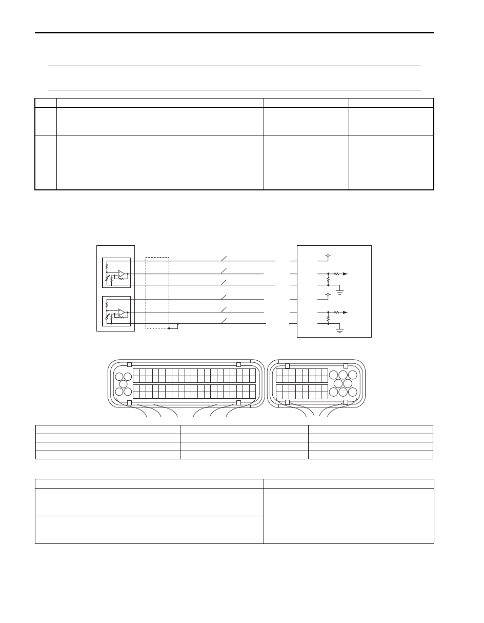
Wiring Diagram
DTC Detecting Condition and Trouble Area
Step
Action
Yes
No
1
Was “Engine and Emission Control System Check”
performed?
Go to Step 2.
Go to “Engine and
Emission Control
System Check”.
2
Electric throttle body assembly check
1) Check electric throttle body for operation and condition
referring to “Electric Throttle Body Assembly On-Vehicle
Inspection in Section 1C”.
Is it in good condition?
Substitute a known
good ECM and recheck.
Repair or replace
electric throttle body
assembly.
1
3 2
4
5
6
7
8
9
1110
12
13
14
15
16
17
18
19
20
17
18
19
20
21
22
23
24
25
26
27
28
29
30
31
33
34
35
36
37
38
39
40
32
1
2
3
4
5
6
7
8
9
10
11
12
13
14
15
16
21
22
23
24
25
26
27
28
29
30
31
32
33
34
35
36
37
38
39
40
41
42
43
44
45
46
47
48
49
50
51
52
53
54
55
56
57
58
59
60
61
62
63
64
65
66
67
68
69
70
71
72
73
74
75
76
77
78
79
80
81
E23
C37
E23-26
E23-27
5 V
WHT/BLU
ORN
1
2
5
4
3
5 V
E23-25
WHT
E23-33
E23-34
E23-35
ORN/BLU
BLU/GRN
BLU/YEL
P
S
G
P1
S1
G1
I6JB01110059-02
P: APP sensor (main) power supply circuit
S1: APP sensor (sub) signal circuit
3: APP sensor (sub)
S: APP sensor (main) signal circuit
G1: APP sensor (sub) ground circuit
4: ECM
G: APP sensor (main) ground circuit
1: APP sensor assembly
5: Ground of APP sensor for shield wire
P1: APP sensor (sub) power supply circuit
2: APP sensor (main)
DTC detecting condition
Trouble area
DTC P2122: Pedal Position Sensor (Main) Circuit Low
Output voltage of pedal position sensor (main) is less than 0.45 V.
(1 driving cycle detection logic)
• APP sensor and its circuit
• ECM
DTC P2123: Pedal Position Sensor (Main) Circuit High
Output voltage of pedal position sensor (main) is more than 4.8 V.
(1 driving cycle detection logic)

Engine General Information and Diagnosis: 1A-154
DTC Confirmation Procedure
1) With ignition switch turned OFF, connect scan tool.
2) Turn ON ignition switch and clear DTC by using scan tool if any.
3) Keep the accelerator pedal at idle position for 2 seconds.
4) Keep the accelerator pedal at fully depressed position for 2 seconds.
5) Repeat Step 3) and 4) for 3 times.
6) Check DTC by using scan tool.
DTC Troubleshooting
NOTE
Before this trouble shooting is performed, read the precautions for DTC troubleshooting referring to
“Precautions on Engine Service”.
Step
Action
Yes
No
1
Was “Engine and Emission Control System Check”
performed?
Go to Step 2.
Go to “Engine and
Emission Control
System Check”.
2
Accelerator pedal position (APP) sensor assembly
mounting check
1) Check that APP sensor assembly has been mounted to
vehicle body properly (no pinched floor carpet, etc.).
Is it in good condition?
Go to Step 3.
Reinstall accelerator
pedal position (APP)
sensor assembly
properly referring to
“Accelerator Pedal
Position (APP) Sensor
Assembly Removal and
Installation in Section
1C”.
3
APP sensor (main) and its circuit check
1) Connect scan tool to DLC with ignition switch turned
OFF.
2) Turn ON ignition switch, check “APP Sensor 1 Volt”
displayed on scan tool when accelerator pedal is idle
position and fully depressed.
Is displayed APP sensor value as described voltage in “Scan
Tool Data”?
Intermittent trouble.
Check for intermittent
referring to “Intermittent
and Poor Connection
Inspection in Section
00”.
Go to Step 4.

1A-155 Engine General Information and Diagnosis:
DTC P2127 / P2128: Pedal Position Sensor (Sub) Circuit Low / High
S6JB0B1104064
Wiring Diagram
Refer to “DTC P2122 / P2123: Pedal Position Sensor (Main) Circuit Low / High”.
DTC Detecting Condition and Trouble Area
DTC Confirmation Procedure
1) With ignition switch turned OFF, connect scan tool.
2) Turn ON ignition switch and clear DTC by using scan tool if any.
3) Keep the accelerator pedal at idle position for 2 seconds.
4) Keep the accelerator pedal at fully depressed position for 2 seconds.
5) Repeat Step 3) and 4) for 3 times.
6) Check DTC by using scan tool.
4
Wire harness check
1) Turn ignition switch OFF position.
2) Disconnect connectors from APP sensor and ECM.
3) Check for proper terminal connection to APP sensor and
ECM connectors.
4) If connections are OK, check that APP sensor (main)
circuit is as follows.
• Wiring harness resistance of each APP sensor (main)
power supply, signal and ground circuit is less than 3
Ω
• Insulation resistance of each APP sensor (main)
power supply and signal circuit is infinity between
APP sensor connector and vehicle body ground.
• Insulation resistance of wire harness is infinity
between APP sensor (main) power supply terminal
and each other terminal at APP sensor connector.
• Circuit voltage of each APP sensor (main) power
supply, signal and ground circuit is 0 – 1 V with
ignition switch turned ON
Are they in good condition?
Go to Step 5.
Repair or replace APP
sensor (main) power
supply, signal and/or
ground circuit(s).
5
APP sensor power supply voltage check
1) Connect connectors to ECM.
2) Turn ignition switch ON position.
3) Check that circuit voltage is 5 V between APP sensor
(main) power supply terminal and vehicle body ground.
Is it in good condition?
Go to Step 5.
Substitute a known
good ECM and recheck.
6
APP sensor check
1) Check APP sensor for performance referring to
“Accelerator Pedal Position (APP) Sensor Assembly
Removal and Installation in Section 1C”.
Is it in good condition?
Substitute a known
good ECM and recheck.
Replace APP sensor
assembly.
Step
Action
Yes
No
DTC detecting condition
Trouble area
DTC P2127: Pedal Position Sensor (Sub) Circuit Low
Output voltage of pedal position sensor (sub) is less than 0.23 V.
(1 driving cycle detection logic)
• APP sensor and its circuit
• ECM
DTC P2128: Pedal Position Sensor (Sub) Circuit High
Output voltage of pedal position sensor (sub) is more than 2.4 V.
(1 driving cycle detection logic)

Engine General Information and Diagnosis: 1A-156
DTC Troubleshooting
NOTE
Before this trouble shooting is performed, read the precautions for DTC troubleshooting referring to
“Precautions for DTC Troubleshooting”.
Step
Action
Yes
No
1
Was “Engine and Emission Control System Check”
performed?
Go to Step 2.
Go to “Engine and
Emission Control
System Check”.
2
APP sensor assembly mounting check
1) Check that APP sensor assembly has been mounted to
vehicle body properly (no pinched floor carpet, etc.).
Is it in good condition?
Go to Step 3.
Reinstall APP sensor
assembly properly
referring to “Accelerator
Pedal Position (APP)
Sensor Assembly
Removal and
Installation in Section
1C”.
3
APP sensor (sub) and its circuit check
1) Connect scan tool to DLC with ignition switch turned
OFF.
2) Turn ON ignition switch, check “APP Sensor 2 Volt”
displayed on scan tool when accelerator pedal is idle
position and fully depressed.
Is displayed APP sensor value as described voltage in “Scan
Tool Data”?
Intermittent trouble.
Check for intermittent
referring to “Intermittent
and Poor Connection
Inspection in Section
00”.
Go to Step 4.
4
Wire harness check
1) Turn ignition switch OFF position.
2) Disconnect connectors from APP sensor and ECM.
3) Check for proper terminal connection to APP sensor and
ECM connectors.
4) If connections are OK, check that APP sensor (sub)
circuit is as follows.
• Wiring harness resistance of each APP sensor (sub)
power supply, signal and ground circuit is less than
3
Ω
• Insulation resistance of each APP sensor (sub) power
supply and signal circuit is infinity between AAP
sensor connector and vehicle body ground.
• Insulation resistance of wire harness is infinity
between APP sensor (sub) power supply terminal and
each other terminal at APP sensor connector.
• Circuit voltage of each APP sensor (sub) power
supply, signal and ground circuit is 0 – 1 V with
ignition switch turned ON
Are they in good condition?
Go to Step 5.
Repair or replace APP
sensor (sub) power
supply, signal and/or
ground circuit(s).
5
APP sensor power supply voltage check
1) Connect connectors to ECM.
2) Turn ignition switch ON position.
3) Check that circuit voltage is 5 V between APP sensor
(sub) power supply terminal and vehicle body ground.
Is it in good condition?
Go to Step 5.
Substitute a known
good ECM and recheck.
Нет комментариевНе стесняйтесь поделиться с нами вашим ценным мнением.
Текст