Suzuki Grand Vitara JB627. Manual — part 80
1D-1 Engine Mechanical:
Engine
Engine Mechanical
General Description
Engine General Information
S6JB0B1401001
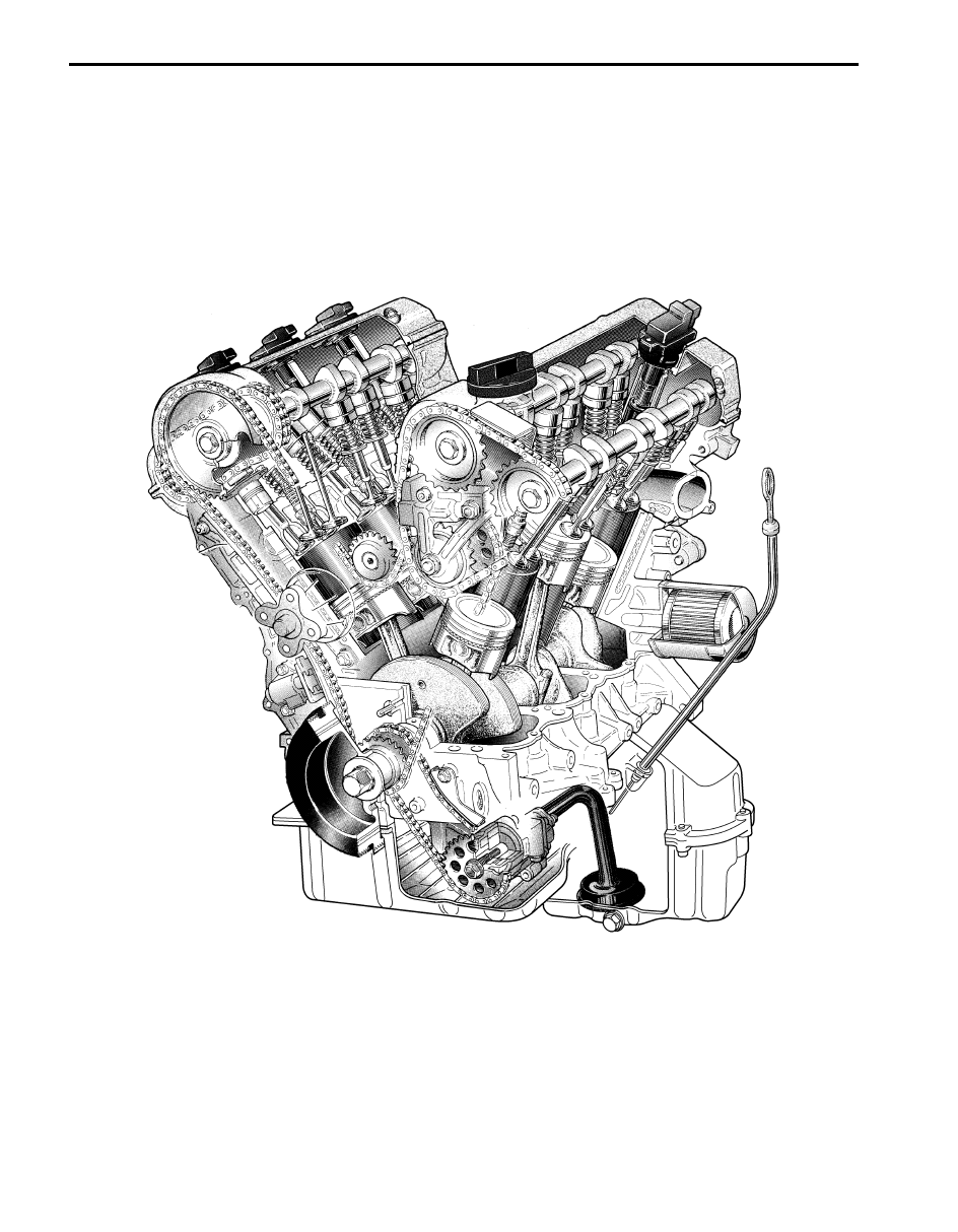
The engine is a water-cooled, 60
° V6 cylinders, 4 stroke cycle gasoline unit with its DOHC (Double over head
camshaft) valve mechanism arranged for “V” type valve configuration. The double overhead camshaft is mounted over
the cylinder head; it is driven from crankshaft through timing chains, and no push rods are provided in the valve train
system.
I6JB01140001-02
Engine Mechanical: 1D-2
Air Cleaner Filter Introduction
S6JB0B1401002
This air cleaner filter is of dry type. Note that it needs cleaning referring to “Air Cleaner Filter Inspection and Cleaning”.
IMT (Intake Manifold Tuning) System Description
S6JB0B1401003
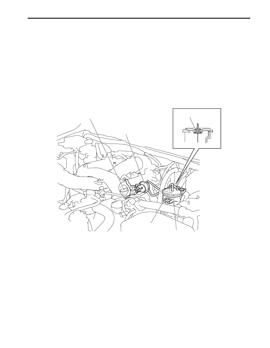
IMT system consists of the following items:
• IMT valve (1) installed between intake manifold and surge tank pipe
• IMT valve actuator (4)
• IMT vacuum solenoid valve (2)
• Vacuum tank (3)
Vacuum tank contains the one way check valve (5) to maintain negative pressure constantly regardless of variation in
the intake manifold pressure.
Vacuum tank, therefore, supplies IMT vacuum solenoid valve actuator with stable negative pressure in whole engine
speed ranges.
1
4
5
3
2
I6JB01140110-01
1D-3 Engine Mechanical:
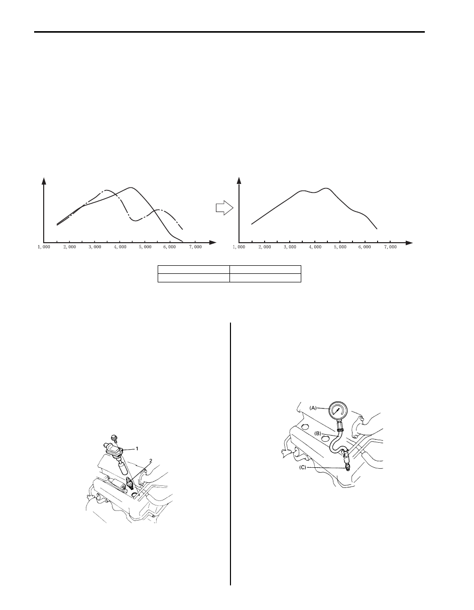
IMT system varies the effective length of intake pipe by opening and closing IMT valve in order to improve an air
volumetric efficiency.
When IMT valve is fully open [A]:
The effective length of intake pipe is short.
With this condition, the engine torque is large at low and middle-high engine speed ranges.
However, the engine torque is small at middle-low and high engine speed ranges.
When IMT valve is totally closed [B]:
The effective length of intake pipe is long.
With this condition, the engine torque is large at middle-low and high engine speed ranges.
However, the engine torque is small at low and middle-high engine speed ranges.
IMT system utilizes this characteristic of engine. IMT valve is opened at low and middle-high engine speed ranges,
and closed at middle-low and high engine speed ranges.
In this way, engine torque is improved in whole engine speed ranges.
Diagnostic Information and Procedures
Compression Check
S6JB0B1404001
Check compression pressure on all 6 cylinders as
follows:
1) Warm up engine.
2) Stop engine after warming up.
3) Remove surge tank cover and disconnect ignition
coil harness couplers.
4) Remove all ignition coils (1) and spark plugs (2)
referring to “Spark Plug Removal and Installation in
Section 1H”.
5) Disconnect fuel injector wire harness at connector.
6) Install special tool (Compression gauge) into spark
plug hole.
Special tool
(A): 09915–64512
(B): 09915–64530
(C): 09915–67010
[A]
[A]+[B]
[B]
1
1
2
2
min-1
(rpm)
min-1
(rpm)
I6JB01140111-01
[A]: IMT valve open
1. Engine torque
[B]: IMT valve closed
2. Engine speed
IYSQ01143002-01
IYSQ01143003-01
Engine Mechanical: 1D-4
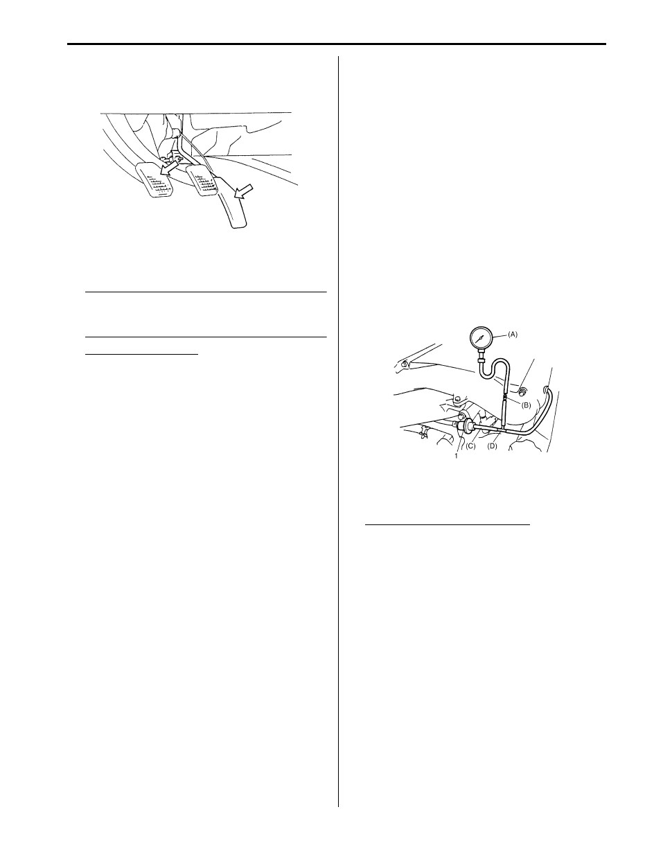
7) Disengage clutch (to lighten starting load on engine)
for M/T vehicle, and depress accelerator pedal all
the way to make throttle fully open.
8) Crank engine with fully charged battery, and read the
highest pressure on compression gauge.
NOTE
For measuring compression pressure, crank
engine at least 250 rpm by using fully
charged battery.
Compression pressure
Standard: 1400 – 1600 kPa (14.0 – 16.0 kg/cm
2
,
199.0 – 227.5 psi)
Limit: 1100 kPa (11.0 kg/cm
2
, 156.0 psi)
Max. difference between any two cylinders: 100
kPa (1.0 kg/cm
2
, 14.2 psi)
9) Carry out steps 6), 7) and 8) on each cylinder to
obtain 6 readings.
Engine Vacuum Check
S6JB0B1404002
The engine vacuum that develops in the intake line is a
good indicator of the condition of the engine. The
vacuum checking procedure is as follows:
1) Warm up engine to normal operating temperature
and make sure that engine idle speed is within
specification.
2) Stop engine and disconnect vacuum hoses from fuel
pressure regulator valve (1).
3) Connect special tools (Vacuum gauge and hose
joint) and 3-way joint between vacuum hose and
valve.
Special tool
(A): 09915–67311
(B): 09918–08210
(C): 09355–35754–600 Hose, SUZUKI genuine
parts
(D): 09367–04002 3-way joint, SUZUKI genuine
parts
4) Start engine and run engine at specified idle speed,
and read vacuum gauge. Vacuum should be within
specification.
Vacuum specifications (sea level)
59 – 79 kPa (450 – 600 mmHg, 17.7 – 23.7 in.Hg)
at specified idle speed
5) After checking, remove, all special tools.
6) Connect vacuum hoses to fuel pressure regulator
valve.
I2RH01140004-01
I4JA01140028-01
Нет комментариевНе стесняйтесь поделиться с нами вашим ценным мнением.
Текст