Suzuki Grand Vitara JB627. Manual — part 372

9B-13 Lighting Systems:
Back-Up Light Symptom Diagnosis
S6JB0B9204011
Brake Light Symptom Diagnosis
S6JB0B9204012
Front Fog Light Symptom Diagnosis (If Equipped)
S6JB0B9204013
NOTE
• Use of SUZUKI scan tool makes it easy to check whether a faulty condition is on the input side or
output side of BCM. For checking procedure, refer to “Diagnosis Using Output Test Function of
SUZUKI Scan Tool” under “Scan Tool Data in Section 10B”.
• Check each part in the order from the top of the following list.
Rear Fog Light Symptom Diagnosis (If Equipped)
S6JB0B9204014
Condition
Possible cause
Correction / Reference Item
Back-up lights do not
light up
Bulb(s) blown
Replace bulb(s).
Circuit fuse blown
Replace fuse and check for short circuit.
Back-up light switch (M/T model) or
transmission range sensor (A/T model)
faulty
Check back-up light switch or transmission
range sensor referring to “Back Up Light
Switch Inspection in Section 5B” or
“Transmission Range Sensor Inspection and
Adjustment in Section 5A”.
Wiring or grounding faulty
Repair circuit.
Back-up lights stay on
Back-up light switch (M/T model) or
transmission range sensor (A/T model)
faulty
Check back-up light switch or transmission
range sensor referring to “Back Up Light
Switch Inspection in Section 5B” or
“Transmission Range Sensor Inspection and
Adjustment in Section 5A”.
Condition
Possible cause
Correction / Reference Item
Brake light do not light up Bulb(s) blown
Replace bulb(s).
Circuit fuse blown
Replace fuse and check for short circuit.
Brake light switch faulty
Check brake light switch referring to “Brake
Light Switch Inspection”.
Wiring or grounding faulty
Repair circuit.
Brake light stay on
Brake light switch faulty
Check or adjust brake light switch referring to
“Brake Light Switch Inspection” or “Brake Light
Switch Adjustment in Section 4A”.
Condition
Possible cause
Correction / Reference Item
Only one light does not
light
Bulb blown
Replace bulb.
Wiring or grounding faulty
Repair circuit.
Front fog lights do not
light
Circuit fuse blown
Replace fuse and check for short circuit.
Bulbs blown
Replace bulbs.
Front fog light switch faulty
Check front fog light switch referring to “Front
Fog Light Switch Inspection (If Equipped)”.
Front fog light relay faulty
Check front fog light relay referring to “Front
Fog Light Relay Inspection (If Equipped)”.
Wiring or grounding faulty
Repair circuit.
BCM faulty
Check BCM for function referring to “Inspection
of BCM and Its Circuits in Section 10B”.
Condition
Possible cause
Correction / Reference Item
Rear fog light do not light Circuit fuse blown
Replace fuse and check for short circuit.
Bulb blown
Replace bulb.
Rear fog light switch faulty
Check rear fog light switch referring to “Rear
Fog Light Switch Inspection (If Equipped)”.
Wiring or grounding faulty
Repair circuit.
Lighting Systems: 9B-14
Illumination Control System Symptom Diagnosis (If Equipped)
S6JB0B9204015
Interior Light Symptom Diagnosis
S6JB0B9204016
NOTE
• Use of SUZUKI scan tool makes it easy to check whether a faulty condition is on the input side or
output side of BCM. For checking procedure, refer to “Diagnosis Using Output Test Function of
SUZUKI Scan Tool” under “Scan Tool Data in Section 10B”.
• Check each part in the order from the top of the following list.
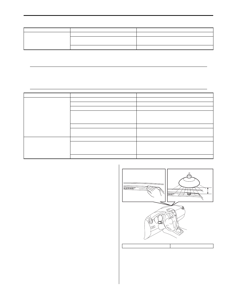
Auto-On Headlight Operation Inspection (If
Equipped)
S6JB0B9204017
1) Turn ignition switch to ON position and then turn
lighting switch to “AUTO” position.
2) Release parking brake lever.
3) Check headlights for operation as follows. If
headlights do not turn ON or OFF, go to “Auto-On
Headlight System Symptom Diagnosis (If
Equipped)”.
a) Cover auto-on headlight sensor by hand and
check that headlights light up then.
b) Light over auto-on headlight sensor vertically
with on incandescent light of approx, 100 W
apart from about 100 mm (3.94 in.) (1) and check
that headlights go off then.
c) In the state as described in Step a), pull up
parking brake lever and check that headlights go
off then.
Condition
Possible cause
Correction / Reference Item
Illumination cancel do not
normal operation
Combination meter faulty
Replace combination meter.
Audio unit and/or information display
(clock) faulty
Replace audio unit and/or information display
(clock).
Wiring or grounding faulty
Repair circuit.
Condition
Possible cause
Correction / Reference Item
Dome light does not light
up
Bulb blown
Replace bulb.
Circuit fuse blown
Replace fuse and check for short circuit.
Dome light switch faulty
Check dome light switch.
Door switch faulty
Check door switch referring to “Door Switch
(Front / Rear / Rear End Door) Inspection in
Section 9C”.
Wiring or grounding
Repair circuit.
BCM faulty
Replace after making sure that none of above
parts is faulty.
Luggage compartment
light does not light up (if
equipped)
Bulb blown
Replace bulb.
Back door switch faulty
Check switch referring to “Door Switch (Front /
Rear / Rear End Door) Inspection in Section
9C”.
Wiring or grounding faulty
Repair circuit.
[A]: Fig. for Step a)
[B]: Fig. for Step b)
[A]
[B]
1
I5JB0A920013-02

9B-15 Lighting Systems:
DRL Operation Inspection (If Equipped)
S6JB0B9204018
1) Confirm that lighting switch is in OFF position.
2) Confirm that dimmer and passing switch is in low beam position.
3) Check DRL for operation as follows.
a) Turn ignition switch to ON position and check headlights remain OFF.
b) Start engine and run it at idle speed. Check headlights turn ON at low beam.
c) Switch dimmer and passing switch to high beam position and check headlights remain tuning ON at low beam.
4) If a malfunction is found, go to “DRL System Symptom Diagnosis (If Equipped)”.
Inspection of Headlight Leveling Control Module and Its Circuit (Vehicle Equipped with Auto
Leveling Headlight System)
S6JB0B9204019
Headlight auto leveling control module and its circuits can be checked at headlight auto leveling control module wiring
couplers by measuring voltage and pulse signal.
CAUTION
!
Headlight auto leveling control module cannot be checked by itself. It is strictly prohibited to connect
voltmeter or ohmmeter to headlight auto leveling control module with couplers disconnected from it.
Voltage Check
Check voltage between each terminal of headlight auto leveling control module and vehicle body ground under each
condition. If measured voltage is out of standard value, check circuit (including switch and sensor) of terminal where
voltage was measured.
NOTE
• As each terminal voltage is affected by the battery voltage, confirm that it is 11 V or more when
ignition switch is ON.
• Voltage with asterisk (*) cannot be measured by voltmeter because it is pulse signal. Check it with
oscilloscope if necessary.
V
10
11
12
13
16
17
18
19
20
3
1
5
6
9
21
22
23
24
[A]
I5JB0A920014-02
[A]: Headlight leveling control module connector (viewed from harness side)

Lighting Systems: 9B-16
Terminal
Circuit
Specification
Condition
1
Power source
10 – 14 V
Ignition switch is at ON position.
2
—
—
—
3
Lighting switch
Less than 1.5 V
Lighting switch is at “HEAD”
position.
10 – 14 V
Lighting switch is at OFF position.
4
—
—
—
5
—
—
—
6
Headlight auto leveling indicator
Continuity
For about 3 seconds after ignition
switch is turned on (i.e., headlight
auto leveling indicator is lit up).
No continuity
More than about 3 seconds after
ignition switch is turned on (i.e.,
headlight auto leveling indicator is
not lit up).
7
—
—
—
8
—
—
—
9
Ground for headlight auto leveling
control unit
0 V
Ignition switch is at ON position.
10
Power supply for right headlight
leveling actuator
10 – 14 V
Ignition switch is at ON position.
11
Power supply for left headlight
leveling actuator
10 – 14 V
Ignition switch is at ON position.
12
Power supply for rear height
sensor
About 5 V
Ignition switch is at ON position.
13
Power supply for front height
sensor
About 5 V
Ignition switch is at ON position.
14
—
—
—
15
—
—
—
16
Vehicle speed signal
Refer to “Reference waveform No.1: ”.
17
Signal for right headlight leveling
actuator
Less than 1 V
Lighting switch is at OFF position.
1.0 – 12.6 V
For 10 seconds after turning
lighting switch to ON position.
18
Signal for left headlight leveling
actuator
Less than 1 V
Lighting switch is at OFF position.
1.0 – 12.6 V
For 10 seconds after turning
lighting switch to ON position.
19
Input signal for rear height sensor
About 2.5 V
Ignition switch is at ON position.
20
Input signal for front height sensor
About 2.5 V
Ignition switch is at ON position.
21
Ground for rear height sensor
0 V
Ignition switch is at ON position.
22
Ground for front height sensor
0 V
Ignition switch is at ON position.
23
Ground for right headlight leveling
actuator
0 V
Ignition switch is at ON position.
24
Ground for left headlight leveling
actuator
0 V
Ignition switch is at ON position.
Нет комментариевНе стесняйтесь поделиться с нами вашим ценным мнением.
Текст