Suzuki Grand Vitara JB627. Manual — part 18

1A-21 Engine General Information and Diagnosis:
C37-57
Ignition coil No.1 output
C37-58
Ground for ECM
C37-59
Ground for ECM
C37-60
—
C37-61
—
C37-62
—
C37-63
—
C37-64
Ground for throttle position sensor
C37-65
Throttle position sensor signal (sub)
C37-66
CMP sensor signal
C37-67
Ground for MAP sensor (if equipped), A/C refrigerant pressure sensor (if equipped), ECT sensor, IAT
sensor and HOS2 (if equipped)
C37-68
MAP sensor signal (if equipped)
C37-69
—
C37-70
—
C37-71
—
C37-72
—
C37-73
Ground for ECM
C37-74
Ignition coil No.6 output
C37-75
Ignition coil No.4 output
C37-76
Ignition coil No.2 output
C37-77
Heater output of A/F sensor (Bank-1)
C37-78
Heater output of A/F sensor (Bank-2)
C37-79
Ground for A/F sensor heater
C37-80
Ground for ECM
C37-81
Ground for ECM
Terminal
Circuit

Engine General Information and Diagnosis: 1A-22
ECM connector “E23”
Terminal
Circuit
E23-1
Power source for ECM internal memory
E23-2
Main power supply
E23-3
Main power supply
E23-4
Output of throttle actuator (+)
E23-5
Output of throttle actuator (–)
E23-6
Throttle actuator control relay output
E23-7
Power supply of throttle actuator drive circuit
E23-8
Ignition switch signal
E23-9
CAN communication line (active high signal)
E23-10
—
E23-11
Clock signal for immobilizer coil antenna (if equipped)
E23-12
—
E23-13
—
E23-14
Radiator cooling fan relay No.3 output
E23-15
Radiator cooling fan relay No.1 output
E23-16
Main power supply relay output
E23-17
CAN communication line (active low signal)
E23-18
—
E23-19
Serial communication line for immobilizer coil antenna (if equipped)
E23-20
—
E23-21
—
E23-22
—
E23-23
Radiator cooling fan relay No.2 output
E23-24
Fuel pump relay output
E23-25
Output for 5 V power source of APP sensor (main)
E23-26
APP sensor signal (main)
E23-27
Ground for APP sensor (main)
E23-28
Fuel level sensor signal
E23-29
Serial communication line of DLC
E23-30
Brake light switch signal
E23-31
Cruise control main switch signal (if equipped)
E23-32
Brake pedal position switch signal for cruise control system (if equipped)
E23-33
Output for 5 V power source of APP sensor (sub)
E23-34
APP sensor signal (sub)
E23-35
Ground for APP sensor (sub)
E23-36
—
E23-37
A/C compressor relay output (if equipped)
E23-38
Ground for cruise control command switch (if equipped)
E23-39
Cruise control command switch signal (if equipped)
E23-40
Clutch pedal position switch signal for cruise control system (if equipped)
1A-23 Engine General Information and Diagnosis:
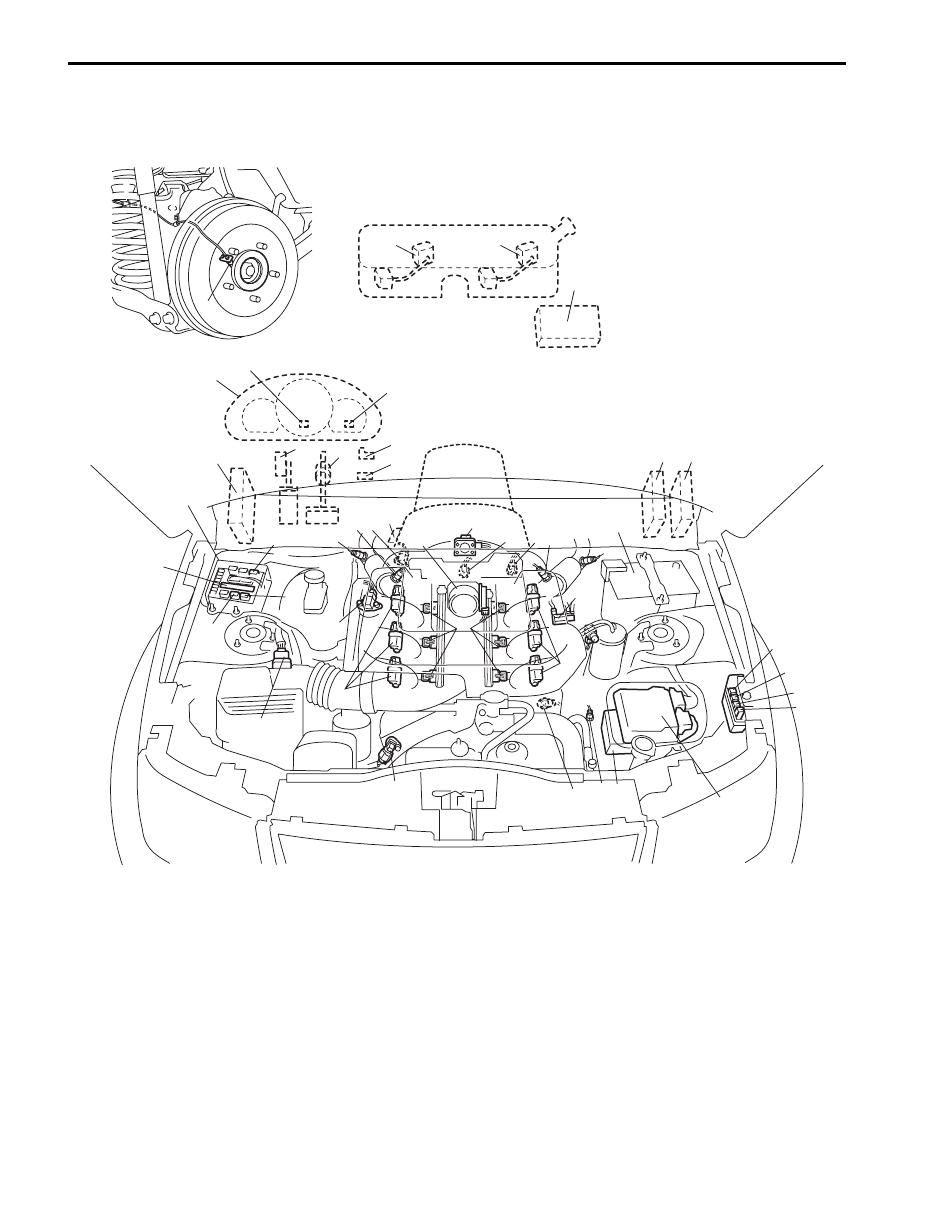
Component Location
Electronic Control System Location
S6JB0B1103001
11
11-1
C
e
n
B
o
f
k
l
15
3
14
I
E
c
m
i
j
J
A
D
K
13
8
g
6
b
5
4
12
d
2
16
10
5
6
7
G
F
1
9
h
a
h
H
7
I5JB0C110005-01

Engine General Information and Diagnosis: 1A-24
Diagnostic Information and Procedures
Engine and Emission Control System Check
S6JB0B1104001
Numbers of each step correspond to the numbers of the items after this table.
Refer to the following items for the detail of each step.
Information sensors
Control devices
Others
1. MAF and IAT sensor
a: Fuel injector
A: ECM
2. Electric throttle body assembly (built-in
throttle position sensor and throttle actuator)
b: EVAP canister purge valve
B: Combination meter
3. Brake light switch
c: Fuel pump relay
C: EVAP canister
4. ECT sensor
d: EGR valve (if equipped)
D: ABS or ESP
® control module
5. A/F sensor (sensor-1)
e: Malfunction indicator lamp
E: Data link connector
6. HO2S (sensor-2) (if equipped)
f: Radiator cooling fan relay No.1
F: 4WD control module
7. Battery
g: IMT vacuum solenoid valve
G: TCM (A/T model)
8. CMP sensor
h: Ignition coil assembly (with ignitor)
H: BCM
9. MAP sensor (if equipped)
i: Main relay
I: Immobilizer coil antenna (if equipped)
10. CKP sensor
j: Integration relay No.2 (built-in HO2S heater relay,
compressor relay and A/T relay)
J: Fuse box No.2
11. Main fuel level sensor
k: Radiator cooling fan relay No.2
K: A/C refrigerant pressure sensor (if equipped)
11-1. Sub fuel level sensor
l: Radiator cooling fan relay No.3
12. Knock sensor
m: Starting motor control relay
13. Power steering pump pressure switch
n: Immobilizer indicator light (if equipped)
14. Accelerator pedal position (APP) sensor
o: Throttle actuator control relay
15. Rear wheel speed sensor (RH, LH) (VSS)
16. Transmission range sensor
Step
Action
Yes
No
1
Customer complaint analysis
1) Perform customer complaint analysis.
Was customer complaint analysis performed?
Go to Step 2.
Perform customer
complaint analysis.
2
DTC / freeze frame data check, record and clearance
1) Check DTC (including pending DTC) referring to “DTC
Is there any malfunction DTC?
Print DTC and freeze
frame data or write them
down and clear them by
referring to “DTC
Clearance”, and go to
Step 3.
Go to Step 4.
3
Visual inspection
1) Perform visual inspection referring to “Visual inspection”.
Is there any faulty condition?
Repair or replace
malfunction part and go
to Step 11.
Go to Step 5.
4
Visual inspection
1) Perform visual inspection referring “Visual inspection”.
Is there any faulty condition?
Repair or replace
malfunction part and go
to Step 11.
Go to Step 8.
5
Trouble symptom confirmation
1) Confirm trouble symptom based on customer complaint
analysis, DTC / freeze frame data in Step 1.
Is trouble symptom identified?
Go to Step 6.
Go to Step 7.
6
Rechecking and record of DTC / freeze frame data
1) Recheck DTC / freeze frame data.
Is there any malfunction DTC?
Go to Step 9.
Go to Step 8.
7
Rechecking and record of DTC / freeze frame data
1) Recheck DTC / freeze frame data.
Is there any malfunction DTC?
Go to Step 9.
Go to Step 10.
Нет комментариевНе стесняйтесь поделиться с нами вашим ценным мнением.
Текст