Suzuki Grand Vitara JB627. Manual — part 432
10E-13 Keyless Start System:
DTC Clearance
S6JB0BA504009
1) Perform Steps 1) through 5) of DTC check procedure
and have DTC indicated.
2) Open driver side door.
3) Close driver side door and within 10 seconds after
that, perform Steps a) to c) described below.
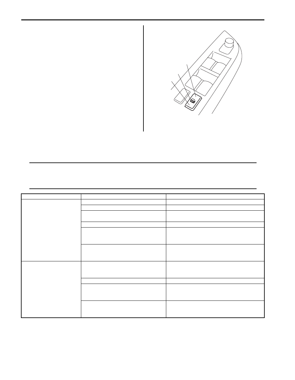
a) Push unlock side (3) of driver side manual door
lock switch (1).
b) Push lock side (2) of driver side manual door
lock switch.
c) Repeat Steps a) and b) 3 times.
At the end of Step c), DTCs are cleared and key
indicator light indicates DTC No. 12 (Normal).
4) After completing DTC clearance, remove ignition key
from ignition key cylinder.
Keyless Start System Symptom Diagnosis
S6JB0BA504010
Door Lock Function of Keyless Start System
NOTE
Before performing trouble diagnosis procedure for door lock function of keyless start system, check
that power door lock system operates properly referring to “Power Door Lock System Operation
Inspection in Section 9F”. If power door lock system does not operate properly, go to “Power Door
Lock System Symptom Diagnosis in Section 9F”.
1
2
3
I5JB0AA50009-02
Condition
Possible cause
Correction / Reference Item
All doors can not be
locked / unlocked by all of
door request switches
Circuit fuse(s) blown
Replace fuse(s) and check for short circuit.
Remote controller battery dead
Replace battery.
Remote controller faulty
Check remote controller for operation referring
to “Remote Controller Inspection”.
Wiring or grounding faulty
Repair circuit.
Antennas or keyless start control
module faulty
Check input and output signals of keyless start
control module referring to “Inspection of
Keyless Start Control Module and Its Circuits”.
BCM faulty
Check input and output signal of BCM referring
to “Inspection of BCM and Its Circuits in
Section 10B”.
All doors can not be
locked / unlocked by any
one of door request
switch
Request switch faulty
Check request switch for operation referring to
“Front Door (Driver and Passenger Side), Rear
End Door Request Switch Inspection”.
Wiring or grounding faulty
Repair circuit.
Antennas or keyless start control
module faulty
Check input and output signals of keyless start
control module referring to “Inspection of
Keyless Start Control Module and Its Circuits”.
BCM faulty
Check input and output signal of BCM referring
to “Inspection of BCM and Its Circuits in
Section 10B”.
Keyless Start System: 10E-14
Keyless Engine Start Function
NOTE
Before performing symptom diagnosis procedure for keyless engine start system, check that engine
starts by using ignition key. If it cannot be started by using ignition key, go to “Engine Symptom
Diagnosis in Section 1A”.
Keyless Start System Operation Inspection
S6JB0BA504011
Keyless engine start operation
1) Sit in driver seat with remote controller carried with you.
2) Check that all doors are closed and ignition key is not inserted in ignition key cylinder.
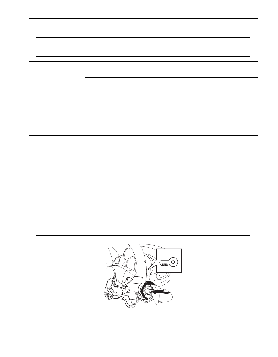
3) While pushing ignition knob switch (1) of steering lock unit, check if ignition knob switch can be turned from its lock
position.
If key indicator light (2) in combination meter lights in blue and ignition knob switch can be turned from its lock
position in this check, keyless engine start operation is in good condition.
If key indicator light in combination meter lights in red and ignition knob switch cannot be turned from its lock
position in this check, go to “Keyless Start System Check”.
NOTE
Pushing ignition knob switch for 5 seconds or longer causes function to protect steering lock
releasing solenoid against heat to work. Then steering lock unit stops energizing solenoid, preventing
ignition knob switch from turning. At the same time, key indicator light in combination meter turns off.
In such case, take your hand off from ignition knob switch once and operate it again.
Condition
Possible cause
Correction / Reference Item
Engine can not be started
by turning Ignition knob
switch
Circuit fuse(s) blown
Replace fuse(s) and check for short circuit.
Remote controller battery dead
Replace battery.
Remote controller faulty
Check remote controller for operation referring
to “Remote Controller Inspection”.
Steering lock unit faulty
Check steering lock unit for operation referring
to “Steering Lock Unit Inspection”.
Wiring or grounding faulty
Repair circuit.
Antennas or keyless start control
module faulty
Check input and output signals of keyless start
control module referring to “Inspection of
Keyless Start Control Module and Its Circuits”.
ECM faulty
Check input and output signal of ECM referring
to “Inspection of ECM and Its Circuits in
Section 1A”.
2
1
I5JB0AA50010-01
10E-15 Keyless Start System:
Door Lock Operation Check (Keyless Start System)
S6JB0BA504012
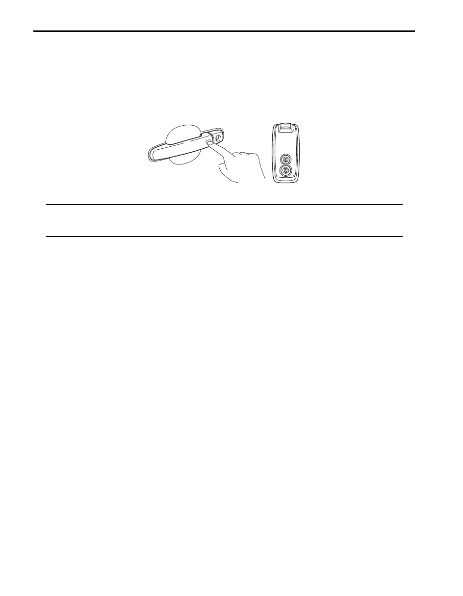
1) Check that all door locks are released and all doors are closed.
2) With remote controller of which ID code is registered in keyless start control module carried with yourself, check
that pushing driver door request switch once locks all doors.
3) Check that pushing request switch of driver door, passenger door or rear end door once releases corresponding
door lock.
4) Check that pushing again request switch pushed in Step 3) releases all door locks.
NOTE
If door of which request switch has been pushed is opened/closed before performing Step 4), all door
locks will not be released even when Step 4) is performed. If Step 4) is performed after door is opened/
closed, only the door of which request switch was pushed will be locked.
I5JB0AA50011-01
Keyless Start System: 10E-16
Inspection of Keyless Start Control Module and Its Circuits
S6JB0BA504013
Keyless start control module and its circuits can be checked at keyless start control module wiring couplers by
measuring voltage and resistance.
CAUTION
!
Keyless start control module cannot be checked by itself. It is strictly prohibited to connect voltmeter
or ohmmeter to keyless start control module with coupler disconnected from it.
Voltage Check
1) Disconnect negative cable (–) at battery.
2) Remove keyless start control module from vehicle body referring to “Keyless Start Control Module Removal and
3) Connect connector to keyless start control module.
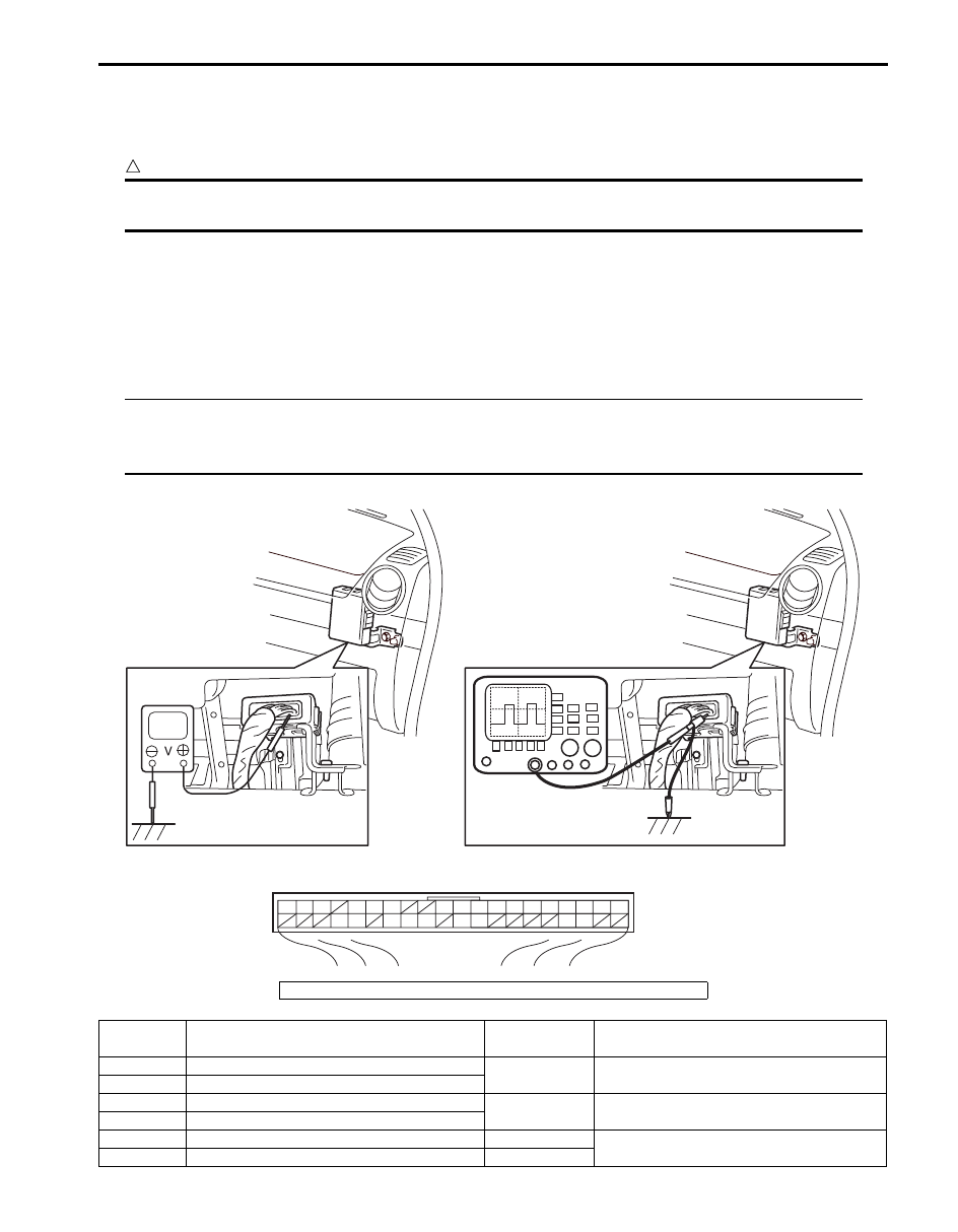
4) Check voltage at each terminal number of couplers connected.
NOTE
• As each terminal voltage is affected by the battery voltage, confirm that it is 11 V or more when
ignition switch is ON.
• Voltage with asterisk (*) cannot be measured by voltmeter because it is pulse signal.
G44
[A]
1
2
3
4
5
6
7
8
9
10
11
14
15
16
36
34 33 32
30 29
24 23
37
18
19
20
I5JB0AA50012-02
[A]: Keyless start control module connector (viewed from harness side)
Terminal
Number
Circuit
Normal
Voltage
Condition
G44-1
Driver side door antenna (–)
*0 – 5 V
Refer to “Reference waveform No. 1: ”
G44-2
Driver side door antenna (+)
G44-3
Rear end door antenna (–)
*0 – 5 V
Refer to “Reference waveform No. 1: ”
G44-4
Rear end door antenna (+)
G44-5
Center antenna (–)
*–1 – 1 V
Refer to “Reference waveform No. 2: ”
G44-6
Center antenna (+)
*–10 – 20 V
Нет комментариевНе стесняйтесь поделиться с нами вашим ценным мнением.
Текст