Suzuki Grand Vitara JB627. Manual — part 63
1A-201 Engine General Information and Diagnosis:
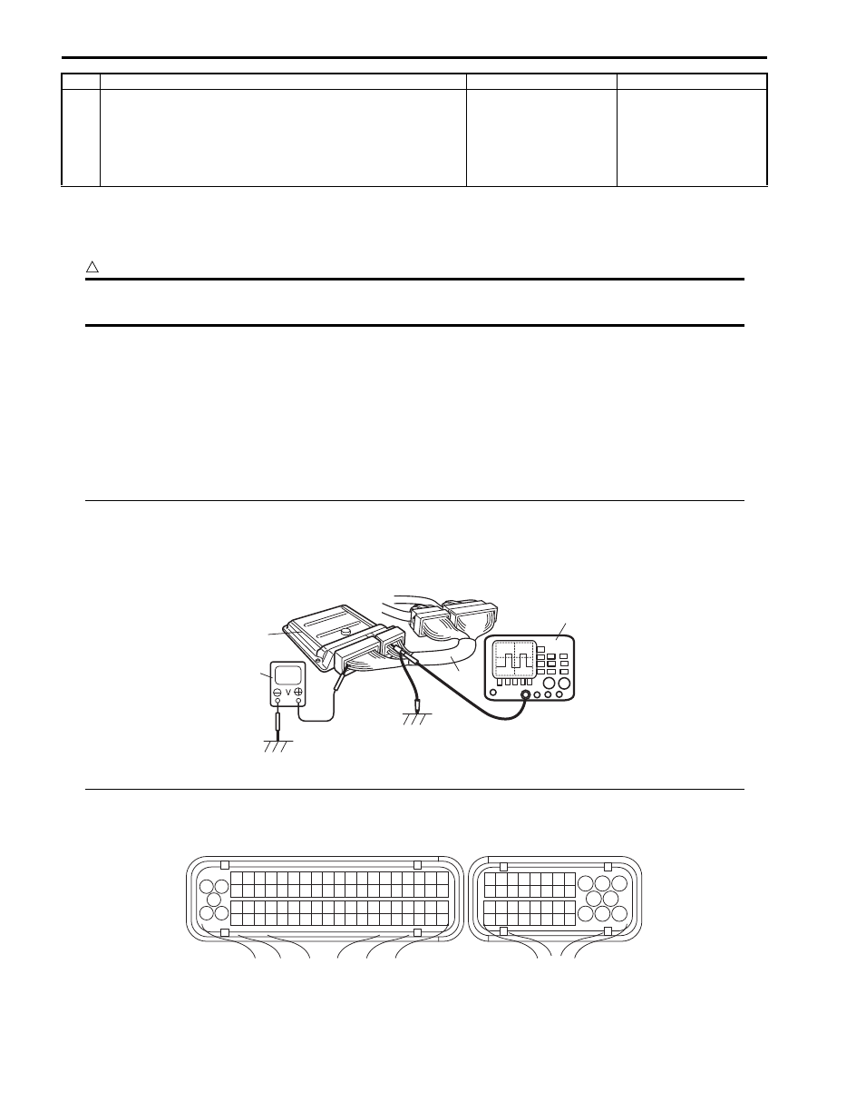
Inspection of ECM and Its Circuits
S6JB0B1104084
ECM and its circuits can be checked by measuring voltage, pulse signal and resistance with special tool connected.
CAUTION
!
ECM cannot be checked by itself. It is strictly prohibited to connect voltmeter or ohmmeter to ECM
with ECM connectors disconnected from it.
Voltage Check
1) Remove ECM (1) from its bracket referring to “Engine Control Module (ECM) Removal and Installation in Section
2) Connect special tool (A) between ECM and ECM connectors securely.
Special tool
(A): 09933–06520
3) Check voltage and/or pulse signal using voltmeter (2) and oscilloscope (3).
NOTE
• As each terminal voltage is affected by battery voltage, confirm that it is 11 V or more when ignition
switch is turned ON.
• Voltage with asterisk (*) cannot be measured with voltmeter because it is pulse signal. Use
oscilloscope for its check if necessary.
• Before performed this inspection, be sure to read the “Precautions of ECM Circuit Inspection”.
Viewed from harness side
17 Combination meter operation check
1) Check combination meter operation for seat belt warning
light by fastening and unfastening driver side seat belt
with ignition switch turned ON.
Is it check result satisfactory?
Substitute a known-
good ECM and recheck.
Check BCM power and
ground circuits, If
circuits are OK,
substitute a known-
good BCM and recheck.
Step
Action
Yes
No
3
2
1
(A)
I6JB01110115-03
1
3 2
4
5
6
7
8
9
1110
12
13
14
15
16
17
18
19
20
17
18
19
20
21
22
23
24
25
26
27
28
29
30
31
33
34
35
36
37
38
39
40
32
1
2
3
4
5
6
7
8
9
10
11
12
13
14
15
16
21
22
23
24
25
26
27
28
29
30
31
32
33
34
35
36
37
38
39
40
41
42
43
44
45
46
47
48
49
50
51
52
53
54
55
56
57
58
59
60
61
62
63
64
65
66
67
68
69
70
71
72
73
74
75
76
77
78
79
80
81
C37
E23
I6JB01110064-02

Engine General Information and Diagnosis: 1A-202
ECM connector “C37”
Terminal
No.
Wire
color
Circuit
Normal voltage
Condition
Remarks
1
BLK/
RED
Heater output of
heated oxygen
sensor-2 (Bank-1)
(if equipped)
10 – 14 V
Ignition switch is at ON
position.
—
*0 – 1 V
↑↓
10 – 14 V
Refer to “Reference
waveform No.1: ” and
“Reference waveform
Engine is running at
specified idle speed after
warmed up engine.
Output signal is active low
duty pulse. Duty ratio
varies depending on the
engine condition.
2
BLK/
RED
Heater output of
heated oxygen
sensor-2 (Bank-1)
(if equipped)
10 – 14 V
Ignition switch is at ON
position.
—
*0 – 1 V
↑↓
10 – 14 V
Refer to “Reference
waveform No.1: ” and
“Reference waveform
Engine is running at
specified idle speed after
warmed up engine.
Output signal is active low
duty pulse. Duty ratio
varies depending on the
engine condition.
3
RED
Oxygen signal of
heated oxygen
sensor-2 (Bank-1)
(if equipped)
4 – 5 V
Ignition switch is at ON
position.
—
Approx. 0.15 V
Refer to “Reference
waveform No.1: ” and
“Reference waveform
Engine is running at
specified idle speed after
warmed up engine.
Output signal varies
depending on the engine
condition.
4
LT GRN MAF sensor signal
0.5 – 1.0 V
Ignition switch is at ON
position.
—
1.2 – 3.6 V
Refer to “Reference
Engine running at
specified idle speed after
warmed up engine.
Output signal varies
depending on the throttle
valve opening and engine
speed.
5
—
—
—
—
—
6
—
—
—
—
—
7
—
—
—
—
—
8
BLU/
RED
Power steering
pump pressure
switch signal
10 – 14 V
Ignition switch is at ON
position.
—
0 – 1 V
Turning steering wheel to
the right or left as far as it
stops while engine is
running.
—
9
—
—
—
—
—
10
GRN/
BLK
EVAP canister
purge valve output
10 – 14 V
Ignition switch is at ON
position.
—
*0 – 0.6 V
↑↓
10 – 14 V
Refer to “Reference
Ignition switch is at ON
position. Set EVAP
canister purge valve at
50% by using “MISC. Test”
of SUZUKI scan tool.
Output signal is active low
duty pulse. Duty ratio
varies depending on the
vehicle condition.
11
YEL/
GRN
EGR valve
(stepper motor coil
3) output (if
equipped)
10 – 14 V
Ignition switch is at ON
position.
—
*0 – 1 V
↑↓
10 – 14 V
Refer to “Reference
Engine is at cranking.
Output signal is active low
duty pulse. Number of
pulse generated times
varies depending on
engine condition.

1A-203 Engine General Information and Diagnosis:
12
YEL/
BLK
EGR valve
(stopper motor coil
1) output (if
equipped)
10 – 14 V
Ignition switch is at ON
position.
—
*0 – 1 V
↑↓
10 – 14 V
Refer to “Reference
Engine is at cranking.
Output signal is active low
duty pulse. Number of
pulse generated times
varies depending on
engine condition.
13
GRY/
GRN
Fuel injector No.5
output
10 – 14 V
Ignition switch is at ON
position.
—
*0 – 0.6 V
↑↓
10 – 14 V
Refer to “Reference
Engine is running at
specified idle speed after
warmed up engine.
Output signal is active low
pulse. Pulse frequency
varies depending on the
engine speed.
Pulse width varies
depending on the ECT
and engine load.
14
PNK/
GRN
Fuel injector No.3
output
10 – 14 V
Ignition switch is at ON
position.
—
*0 – 0.6 V
↑↓
10 – 14 V
Refer to “Reference
Engine is running at
specified idle speed after
warmed up engine.
Output signal is active low
pulse. Pulse frequency
varies depending on the
engine speed.
Pulse width varies
depending on the ECT
and engine load.
15
PNK
Fuel injector No.1
output
10 – 14 V
Ignition switch is at ON
position.
—
*0 – 0.6 V
↑↓
10 – 14 V
Refer to “Reference
Engine is running at
specified idle speed after
warmed up engine.
Output signal is active low
pulse. Pulse frequency
varies depending on the
engine speed.
Pulse width varies
depending on the ECT
and engine load.
16
RED/
BLU
Ground for A/F
sensor adjusting
resister (Bank-1)
Below 0.3 V
Ignition switch is at ON
position.
—
17
RED/
YEL
A/F sensor
adjusting resister
signal (Bank-1)
0.15 – 4.82 V
Ignition switch is at ON
position.
—
18
BLK
A/F sensor signal
(+) (Bank-1)
2.0 – 2.4 V
Refer to “Reference
and “Reference
Engine is running at
specified idle speed after
warmed up engine.
—
19
WHT
A/F sensor signal
(–) (Bank-1)
1.6 – 2.0 V
Refer to “Reference
and “Reference
Engine is running at
specified idle speed after
warmed up engine.
—
Terminal
No.
Wire
color
Circuit
Normal voltage
Condition
Remarks

Engine General Information and Diagnosis: 1A-204
20
WHT/
BLK
Heater output of
heated oxygen
sensor-2 (Bank-2)
(if equipped)
10 – 14 V
Ignition switch is at ON
position.
—
*0 – 1 V
↑↓
10 – 14 V
Refer to “Reference
waveform No.1: ” and
“Reference waveform
Engine is running at
specified idle speed after
warmed up engine.
Output signal is active low
duty pulse. Duty ratio
varies depending on the
engine condition.
21
WHT/
BLK
Heater output of
heated oxygen
sensor-2 (Bank-2)
(if equipped)
10 – 14 V
Ignition switch is at ON
position.
—
*0 – 1 V
↑↓
10 – 14 V
Refer to “Reference
waveform No.1: ” and
“Reference waveform
Engine is running at
specified idle speed after
warmed up engine.
Output signal is active low
duty pulse. Duty ratio
varies depending on the
engine condition.
22
RED
Oxygen signal of
heated oxygen
sensor-2 (Bank-2)
(if equipped)
4 – 5 V
Ignition switch is at ON
position.
Output signal varies
depending on the engine
condition.
Approx. 0.15 V
Refer to “Reference
waveform No.1: ” and
“Reference waveform
Engine is running at
specified idle speed after
warmed up engine.
23
BLU
Ground for MAF
sensor
Below 0.3 V
Ignition switch is at ON
position.
—
24
RED IAT sensor signal
3.62 – 3.93 V
Ignition switch is at ON
position and intake air
temperature is at 0
°C (32
°F)
—
1.85 – 2.02 V
Ignition switch is at ON
position and intake air
temperature is at 40
°C
(104
°F)
—
0.73 – 0.80 V
Ignition switch is at ON
position and intake air
temperature is at 80
°C
(176
°F)
—
25
WHT
Knock sensor
signal
2 – 3 V
Refer to “Reference
Engine is running at 4000
rpm after warmed up
engine.
—
26
PPL/
YEL
ECT sensor signal
3.64 – 3.95 V
Ignition switch is at ON
position and engine
coolant temperature is at 0
°C (32 °F)
—
1.50 – 1.63 V
Ignition switch is at ON
position and engine
coolant temperature is at
50
°C (122 °F)
—
0.45 – 0.49 V
Ignition switch is at ON
position and engine
coolant temperature is at
100
°C (212 °F)
—
27
—
—
—
—
—
Terminal
No.
Wire
color
Circuit
Normal voltage
Condition
Remarks
Нет комментариевНе стесняйтесь поделиться с нами вашим ценным мнением.
Текст