Suzuki Grand Vitara JB627. Manual — part 310
8B-66 Air Bag System:
DTC B1073 / B1077: Driver / Passenger Forward-Sensor Circuit Short to Ground
S6JB0B8204027
Wiring Diagram
CAUTION
!
Be sure to observe instructions under CAUTION in “Air Bag Diagnostic System Check Flow”.
DTC Will Set when
Forward-sensor abnormal signal is detected by SDM.
Flow Test Description
Step 1: Check for short circuit between forward-sensor circuit and ground.
Step 2: Check if malfunction is in forward-sensor.
5V
BLK
G47-20 GND
“G47”
1
2
4
3
RED
BLK/YEL
“G01”
G47-16
IG
[A]
G47-19
G47-11
FP+
FP-
G47-17
G47-9
FD+
FD-
“G47”
ORN
PNK/BLK
ORN
PNK/BLK
“E77”
“G06”
“E24”
“E13”
PNK
PNK/BLU
PNK
PNK/BLU
BLK
G46-16 GND
“G46”
1
2
4
3
RED
BLK/YEL
“G01”
G46-11
IG
[B]
L33-11
L33-12
FP+
FP-
L33-10
L33-9
FD+
FD-
5V
ORN
PNK/BLK
ORN
PNK/BLK
“E79”
“L03”
“E24”
“E13”
PNK
PNK/BLU
PNK
PNK/BLU
“L33”
8
8
5
5
6
6
7
7
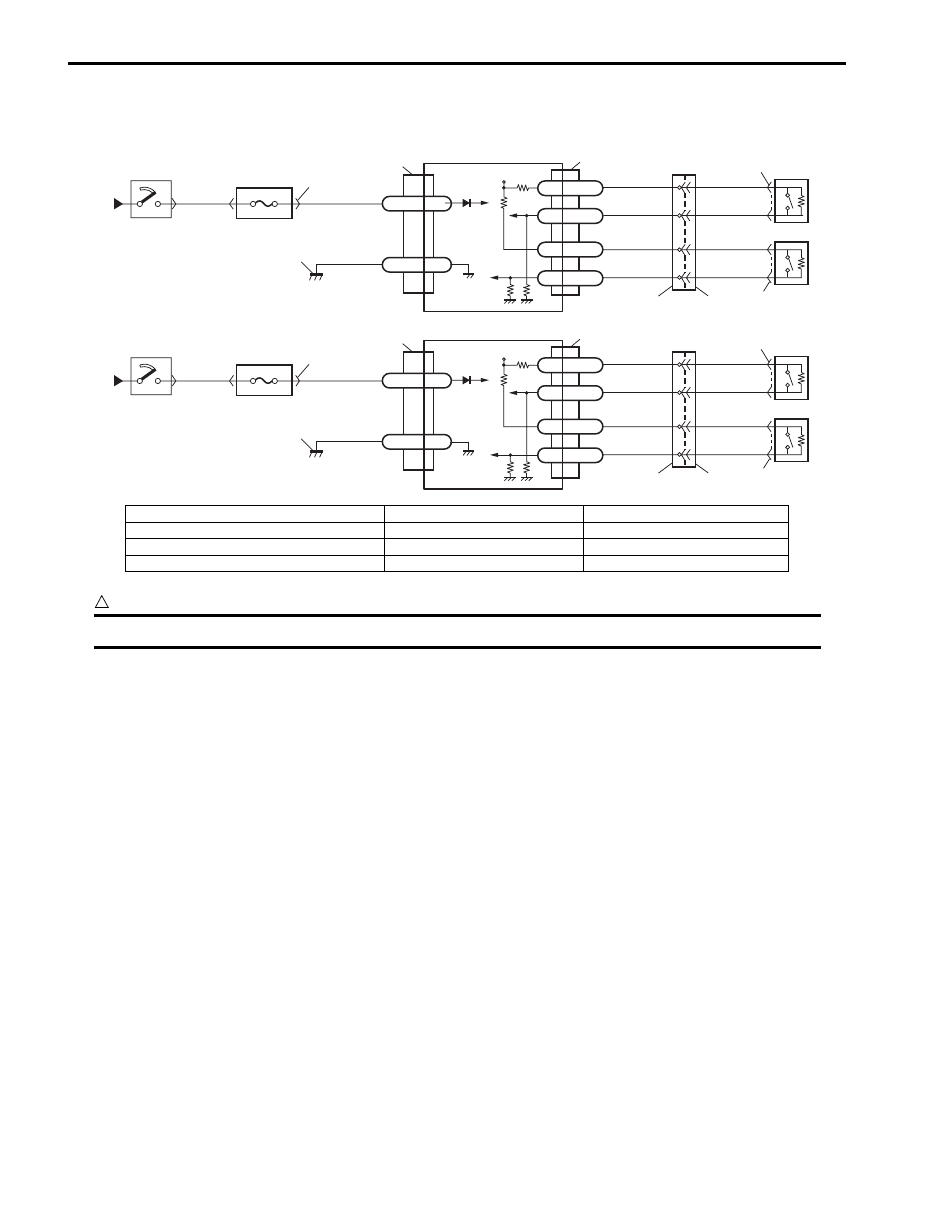
I5JB0A820049-01
[A]: Without side-air bag and curtain-air bag
3. “A/B” fuse
7. Passenger forward-sensor
[B]: With side-air bag and curtain-air bag
4. Junction block assembly
8. Ground for air bag system
1. From main fuse
5. SDM
2. Ignition switch
6. Forward-sensor
Air Bag System: 8B-67
DTC Troubleshooting
NOTE
Upon completion of inspection and repair work, perform the following items.
• Reconnect all air bag system components and ensure all components are properly mounted.
• Clear DTCs referring to “DTC Clearance”, if any.
• Repeat “Air Bag Diagnostic System Check” to confirm that the trouble has been corrected.
Step
Action
Yes
No
1
1) Turn ignition switch to OFF position.
2) Disconnect forward-sensor connector “E13” or “E24”.
3) Disconnect SDM connector “G47” or “L33”.
4) Check proper connection to SDM connector at terminals
“G47-9” and “G47-17” or “L33-9” and “L33-10” (for DTC
B1073) or terminals “G47-11” and “G47-19” or “L33-11”
and “L33-12” (for DTC B1077).
5) Measure resistance between “G47-9” and body ground,
“G47-17” and body ground (for DTC B1073) or “G47-11”
and body ground, “G47-19” and body ground (for DTC
B1077) [A], or between “L33-9” and body ground, “L33-
10” and body ground (for DTC B1073) or “L33-11” and
body ground, “L33-12” and body ground (for DTC
B1077) [B].
Special tool
(A): 09932–76010
Is each measured resistance infinity?
Go to Step 2.
For DTC B1073: “ORN”
circuit or “PNK/BLK”
circuit shorted to
ground.
For DTC B1077: “PNK”
circuit or “PNK/BLU”
circuit shorted to
ground.
2
1) Check forward-sensor referring to “Forward-Sensor
Is it in good condition?
Substitute a known-
good SDM and recheck.
Replace forward-sensor
referring to “Forward-
Sensor Removal and
Installation”. If DTC still
exists, substitute a
known-good SDM and
recheck.
[A]
[B]
“G47-17”
“G47-9”
“G47-19” “G47-11”
“L33-10”
“L33-9”
“L33-11” “L33-12”
(A)
I5JB0A820050-02

8B-68 Air Bag System:
DTC B1074 / B1078: Driver / Passenger Forward-Sensor Circuit Short to Power Circuit or Open
S6JB0B8204028
Wiring Diagram
Refer to “DTC B1073 / B1077: Driver / Passenger Forward-Sensor Circuit Short to Ground”.
CAUTION
!
Be sure to observe instructions under CAUTION in “Air Bag Diagnostic System Check Flow”.
DTC Will Set when
Forward-sensor abnormal signal is detected by SDM.
Flow Test Description
Step 1: Check for open circuit in forward-sensor circuit.
Step 2: Check for short circuit between forward-sensor circuit and power supply circuit.
Step 3: Check if malfunction is in forward-sensor.
DTC Troubleshooting
Step
Action
Yes
No
1
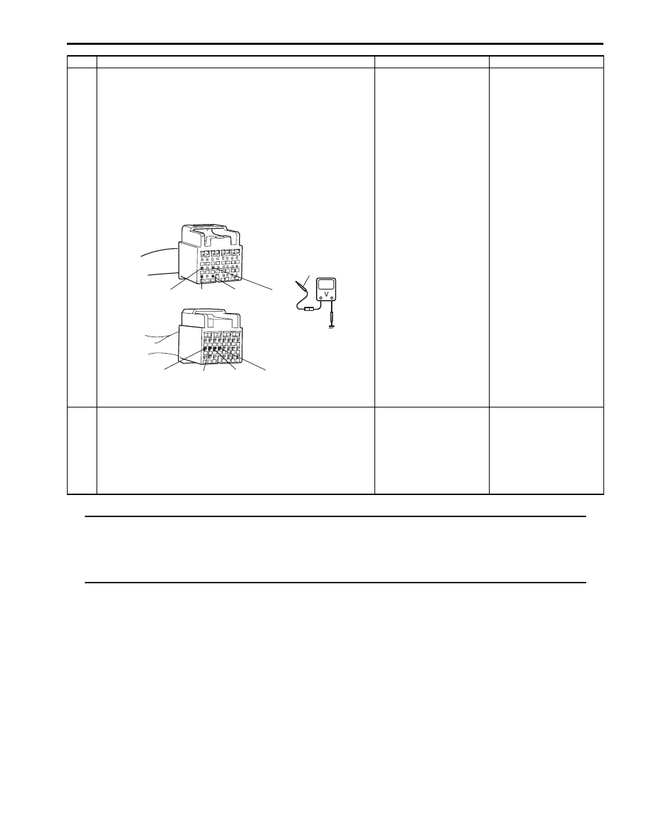
1) Turn ignition switch to OFF position.
2) Disconnect forward-sensor connector “E13” or “E24”.
3) Disconnect SDM connector “G47” or “L33”.
4) Check proper connection to SDM connector at terminals
“G47-9” and “G47-17” or “L33-9” and “L33-10” (for DTC
B1074), or terminals “G47-11” and “G47-19” or “L33-11”
and “L33-12” (for DTC B1078).
5) Check proper connection to forward-sensor connector at
terminals “E13-1” and “E13-2” or “E24-1” and “E24-2”.
6) Using service wire (1), connect “E13-1” and “E13-2”
terminal (for DTC B1074) or “E24-1” and “E24-2”
terminal (for DTC B1078) of forward-sensor connector.
7) Measure resistance between “G47-9” and “G47-17” (for
DTC B1074) or “G47-11” and “G47-19” (for DTC B1078)
[A], or between “L33-9” and “L33-10” (for DTC B1074) or
“L33-11” and “L33-12” (for DTC B1078) [B].
Special tool
(A): 09932–76010
Is each measured resistance 1
Ω
or less?
Go to Step 2.
For DTC B1074: High
resistance or open wire
in “ORN” circuit or
“PNK/BLK” circuit.
For DTC B1078: High
resistance or open wire
in “PNK” circuit or “PNK/
BLU” circuit.
“E13-1”, “E24-1”
“E13-2”, “E24-2”
1
[A]
[B]
“L33-12”
“L33-9” “L33-10” “L33-11”
“G47-9” “G47-17” “G47-19” “G47-11”
(A)
I5JB0A820051-01
Air Bag System: 8B-69
NOTE
Upon completion of inspection and repair work, perform the following items.
• Reconnect all air bag system components and ensure all components are properly mounted.
• Clear DTCs referring to “DTC Clearance”, if any.
• Repeat “Air Bag Diagnostic System Check” to confirm that the trouble has been corrected.
2
1) Disconnect service wire from “E13” or “E24” connector.
2) Measure voltage between “G47-9” and body ground,
“G47-17” and body ground (for DTC B1074) or “G47-11”
and body ground, “G47-19” and body ground (for DTC
B1078) [A], or between “L33-9” and body ground, “L33-
10” and body ground (for DTC B1074) or “L33-11” and
body ground, “L33-12” and body ground (for DTC
B1078) [B].
Special tool
(A): 09932–76010
With ignition switch ON, is each measured value 1 V or less?
Go to Step 3.
For DTC B1074: “ORN”
circuit or “PNK/BLK”
circuit shorted to power
circuit.
For DTC B1078: “PNK”
circuit or “PNK/BLU”
circuit shorted to power
circuit.
3
1) Check forward-sensor referring to “Forward-Sensor
Is it in good condition?
Substitute a known-
good SDM and recheck.
Replace forward-sensor
referring to “Forward-
Sensor Removal and
Installation”. If DTC still
exists, substitute a
known-good SDM and
recheck.
Step
Action
Yes
No
(A)
[A]
[B]
“G47-11”
“G47-9” “G47-17” “G47-19 ”
“L33-9”
“L33-10”
“L33-11” “L33-12”
I5JB0A820052-01
Нет комментариевНе стесняйтесь поделиться с нами вашим ценным мнением.
Текст