Suzuki Grand Vitara JB627. Manual — part 394
9F-4 Security and Locks:
Keyless Entry System Operation Inspection
S6JB0B9604004
NOTE
When preforming the this inspection, make sure to have any of the door once opened / closed after the
ignition key has been removed from the ignition key cylinder.
1) Confirm that power door lock system operates normally, refer to “Power Door Lock System Operation Inspection”.
2) All doors are closed and unlocked.
3) Check the following operation:
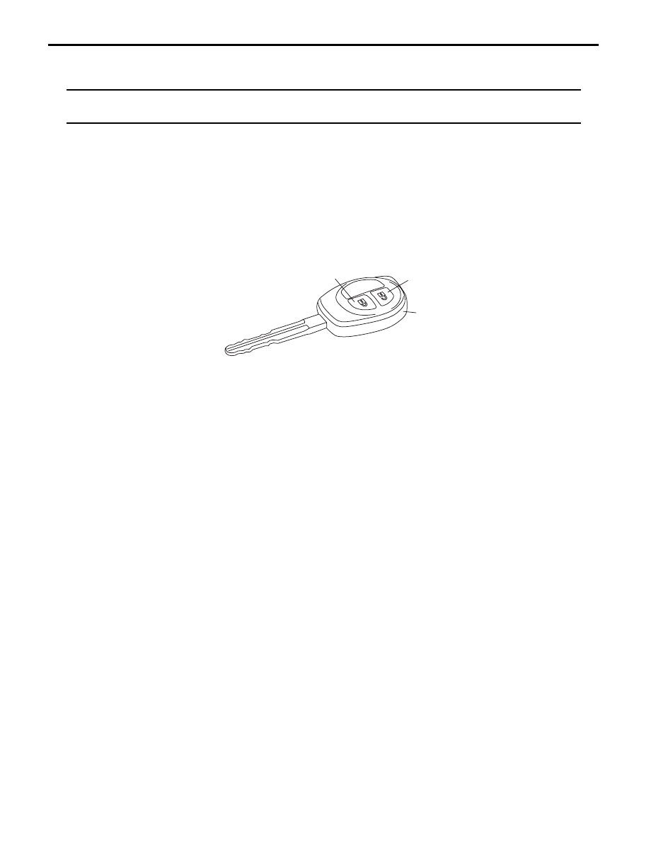
a) Push “lock” button (1) on transmitter (2) or remote controller once, and check all doors lock and hazard waning
lights flash once.
b) Push “unlock” button (3) on transmitter (2) or remote controller twice, and check all doors unlock and hazard
waning lights flash twice and interior light turns on several seconds with the interior light switch in the middle
position.
If malfunction is found, go to “Keyless Entry System Symptom Diagnosis (If Equipped)”.
Door Lock Function of Keyless Start System Symptom Diagnosis (If Equipped)
S6JB0B9604005
Proceed to “Keyless Start System Symptom Diagnosis in Section 10E” in case that doors cannot be locked and
unlocked by operating the request switch at the outside door handle.
1
3
2
I6JB0B960001-01
Security and Locks: 9F-5
Repair Instructions
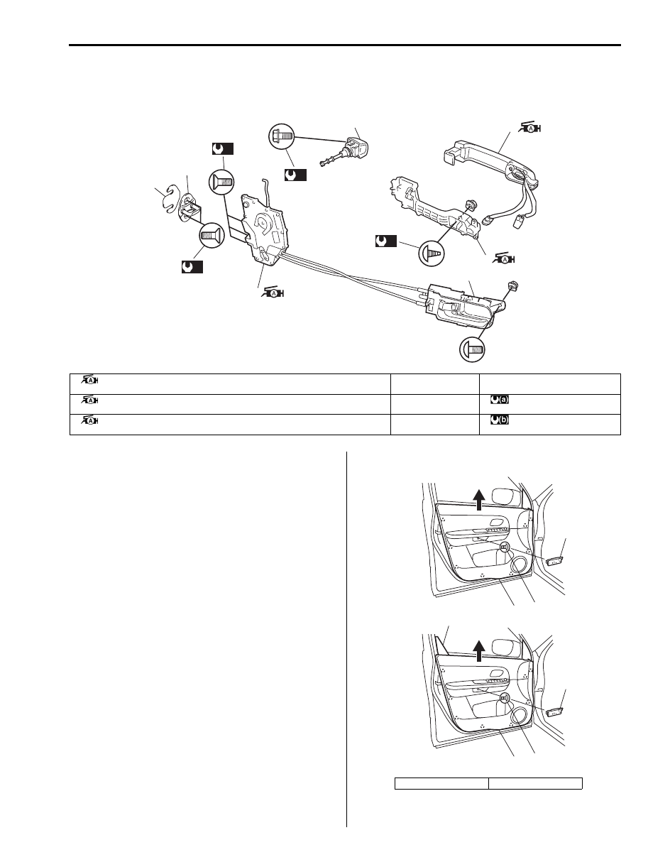
Front Door Lock Assembly Components
S6JB0B9606001
Front Door Lock Assembly Removal and
Installation
S6JB0B9606002
Removal
1) Remove door mirror trim (1), front door inner garnish
(2) (3 door model only) and door trim screw cover
(3).
2) Remove door trim (4) after removing door trim screw
(5) and clips.
(a)
(a)
(a)
(b)
6
3
7
1
4
5
2
I5JB0A960002-02
1. Front door latch assembly
: Apply lithium grease 99000-25011 to sliding and rotating parts and spring if any.
4. Latch striker
7. Inside handle bezel
2. Outside handle assembly
: Apply lithium grease 99000-25011 to sliding part.
5. Shim
: 5.0 N
⋅m (0.5 kgf-m, 4.0 lb-ft)
3. Outside handle frame
: Apply lithium grease 99000-25011 to sliding part and spring.
6. Key cylinder
: 10 N
⋅m (1.0 kgf-m, 7.5 lb-ft)
[A]: 5 door model
[B]: 3 door model
1
3
5
4
2
1
3
5
4
[A]
[B]
I5JB0A950010-01
9F-6 Security and Locks:
3) Disconnect door illumination light lead wire and
power window switch and mirror switch lead wire at
coupler.
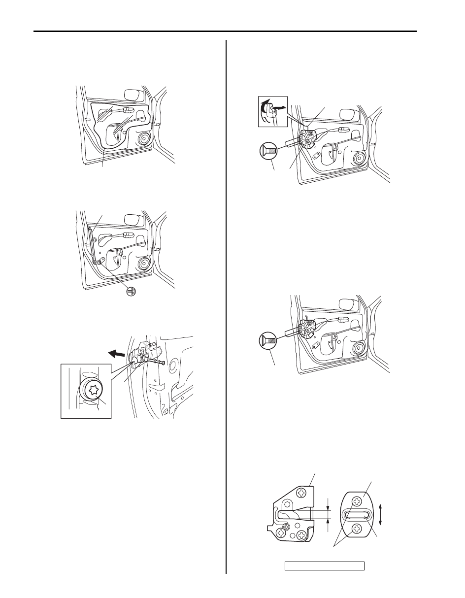
4) Remove door sealing cover (1).
5) Raise window all the way up.
6) Remove door sash (1).
7) Remove key cylinder mounting bolt (1), and then
remove key cylinder (2).
8) Disconnect door opening control rod (1) from outside
handle.
9) Disconnect door lock motor lead wire at coupler.
10) Remove door latch screws (2) and remove door lock
assembly (3).
Installation
Reverse removal procedure to install front door lock
assembly noting the following instructions.
• Apply grease to sliding parts of door latch assembly.
: Grease 99000–25011 (SUZUKI Super Grease A)
• Tighten door latch screws to specified torque.
Tightening torque
Door latch screw (a): 5.0 N·m (0.5 kgf-m, 4.0 lb-ft)
• Move door latch striker (2) up or down so its center
aligns with the center of groove “A” on the door lock
assembly (1) as shown.
Striker should be moved vertically and placed level.
Do not adjust door lock.
Tightening torque
Door latch striker screw (a): 10 N·m (1.0 kgf-m, 7.5
lb-ft)
1
I5JB0A950011-02
1
I5JB0A960003-01
1
2
I4RS0B960005-01
3. Shaft
3
2
1
I5JB0A960004-01
(a)
I5JB0A960005-01
1
2
3
(a)
“A”
I5JB0A960006-01
Security and Locks: 9F-7
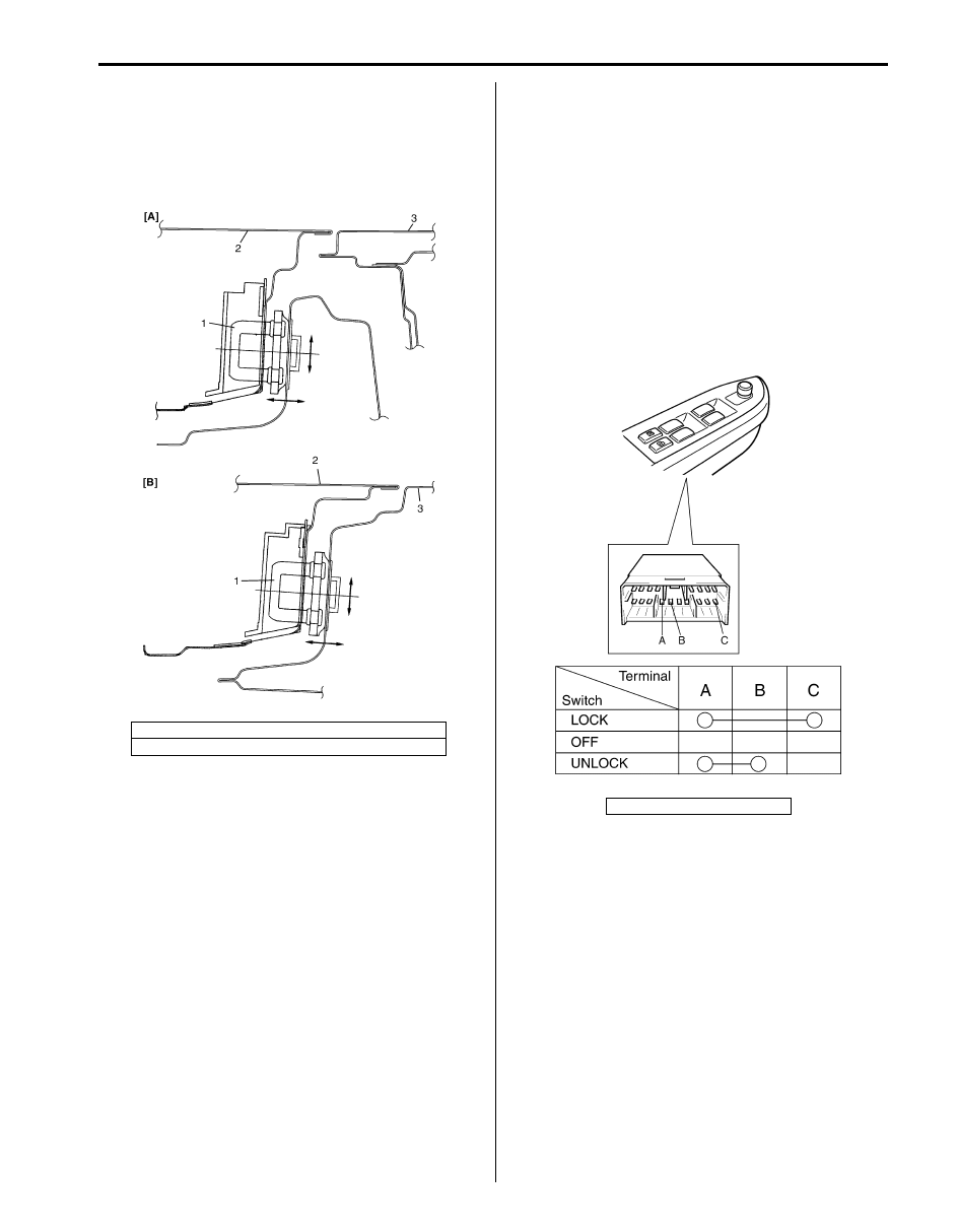
• Move door latch striker (1) sideways to adjust door
outer panel surface (2) flush with rear door outer
panel or body outer panel surface (3) as shown.
In order to correctly obtain door lock operation
increase or decrease number of shims inserted
between body and striker (1) to adjust it.
Front Door Lock Assembly Inspection
S6JB0B9606003
• Check that door open and closes smoothly and
properly.
• Check that door stops in the secondary latched
position properly (preventing door from opening
freely) and that door closed completely in the fully
latched position.
• Adjust door latch striker position, if necessary.
Power Door Lock Switch Inspection
S6JB0B9606004
Check for continuity between terminals at each switch
position. If check result is not as specified, replace
switch.
[A]: Front door (5 door model)
[B]: Rear door (5 door model) or front door (3 door model)
I3RM0A960013-01
1. Power door lock switch
I5JB0A960007-01
Нет комментариевНе стесняйтесь поделиться с нами вашим ценным мнением.
Текст