Suzuki Grand Vitara JB627. Manual — part 89
1D-37 Engine Mechanical:
6) Install camshaft housing pins (3) as shown in figure.
7) Check position of camshaft housings.
Embossed marks are provided on each camshaft
housing, indicating position and direction for
installation. Install housings as indicated by these
marks.
8) After applying oil to housing bolts, tighten them
temporarily first.
Then tighten them by following sequence (“1” – “17”)
as indicated in figure. Tighten a little at a time and
evenly among bolts and repeat tightening sequence
2 or 3 times before they are tightened to specified
torque below.
Tightening torque
Camshaft housing bolt: 11 N
⋅m (1.1 kgf-m, 8.0 lb-
ft) by the specified procedure
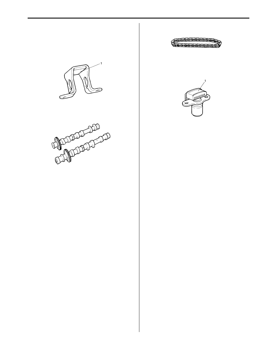
9) Install timing chain guide No.3 (1).
Tightening torque
Timing chain guide No.3 bolt (c): 11 N·m (1.1
kgf-m, 8.0 lb-ft)
10) Install 1st timing chain. Refer to “1st Timing Chain
and Chain Tensioner Removal and Installation”.
11) Install LH (No.1) bank 2nd timing chain. Refer to “LH
(No.1) Bank 2nd Timing Chain and Chain Tensioner
Removal and Installation”.
12) Install timing chain cover. Refer to “Timing Chain
Cover Removal and Installation”.
13) Install oil pans referring to “Oil Pan and Oil Pump
Strainer Removal and Installation in Section 1E”.
14) Install cylinder head covers referring to “Cylinder
Head Covers Removal and Installation”.
15) Install intake manifold, intake collector and electric
throttle body assembly referring to “Intake Collector
and Intake Manifold Removal and Installation” and
“Electric Throttle Body Assembly Removal and
Installation”.
16) Install engine assembly to vehicle referring to
“Engine Assembly Removal and Installation”.
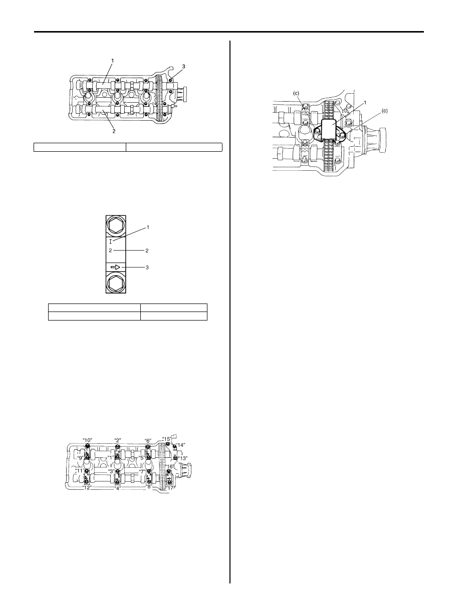
1. RH (No.2) bank intake camshaft
2. RH (No.2) bank exhaust camshaft
1. I: Intake side, E: Exhaust side
3. Timing chain side
2. Position from timing chain side
I6JB01140074-01
IYSQ01143090-01
I6JB01140075-01
I6JB01140076-01
Engine Mechanical: 1D-38
RH (No.2) Bank 2nd Timing Chain and Chain
Tensioner Inspection
S6JB0B1406026
Timing Chain Guide No.3
Check shoe (1) for excessive wear or damage.
If any malfunction is found, replace it.
RH (No.2) Bank 2nd Timing Chain Sprockets
Check teeth of sprocket for wear or damage.
RH (No.2) Bank 2nd Timing Chain
Check timing chain for wear or damage.
Timing Chain Tensioner Adjuster No.2
• Check shoe (1) for wear or damage.
• Check that plunger slides smoothly.
IYSQ01143083-01
IYSQ01143084-01
IYSQ01143085-01
IYSQ01143086-01
1D-39 Engine Mechanical:
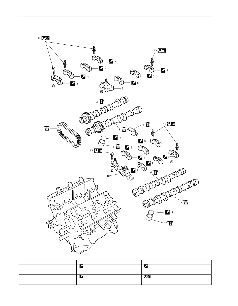
Camshafts, Tappets and Shims Components
S6JB0B1406027
I6JB01140077-01
1. RH (No.2) bank 2nd timing chain
7. LH (No.1) bank exhaust camshaft
13. Camshaft housing bolt
2. RH (No.2) bank exhaust camshaft
8. LH (No.1) bank intake camshaft housing
: Point arrow mark on cap to camshaft
sprocket side.
14. Shim
: Direct shim No. side toward tappet.
3. RH (No.2) bank intake camshaft
9. LH (No.1) bank exhaust camshaft housing
: Point arrow mark on cap to camshaft
sprocket side.
: Tighten 11 Nm (1.1 kgf-m, 8.0 lb-ft) by the
specified procedure.
Engine Mechanical: 1D-40
Camshafts, Tappets and Shims Removal and
Installation
S6JB0B1406028
Removal
1) Remove engine assembly from vehicle referring to
“Engine Assembly Removal and Installation”.
2) Remove timing chain cover. Refer to “Timing Chain
Cover Removal and Installation”.
3) Remove LH (No.1) bank 2nd timing chain. Refer to
“LH (No.1) Bank 2nd Timing Chain and Chain
Tensioner Removal and Installation”.
4) Remove 1st timing chain. Refer to “1st Timing Chain
and Chain Tensioner Removal and Installation”.
5) Remove RH (No.2) bank camshafts. Refer to “RH
(No.2) Bank 2nd Timing Chain and Chain Tensioner
Removal and Installation”.
6) Loosen LH (No.1) bank camshaft housing bolts in
such order (“1” – “17”) as indicated in figure and
remove them.
7) Remove LH (No.1) bank camshaft housings.
8) Remove LH (No.1) bank camshafts.
9) Remove tappets with shims.
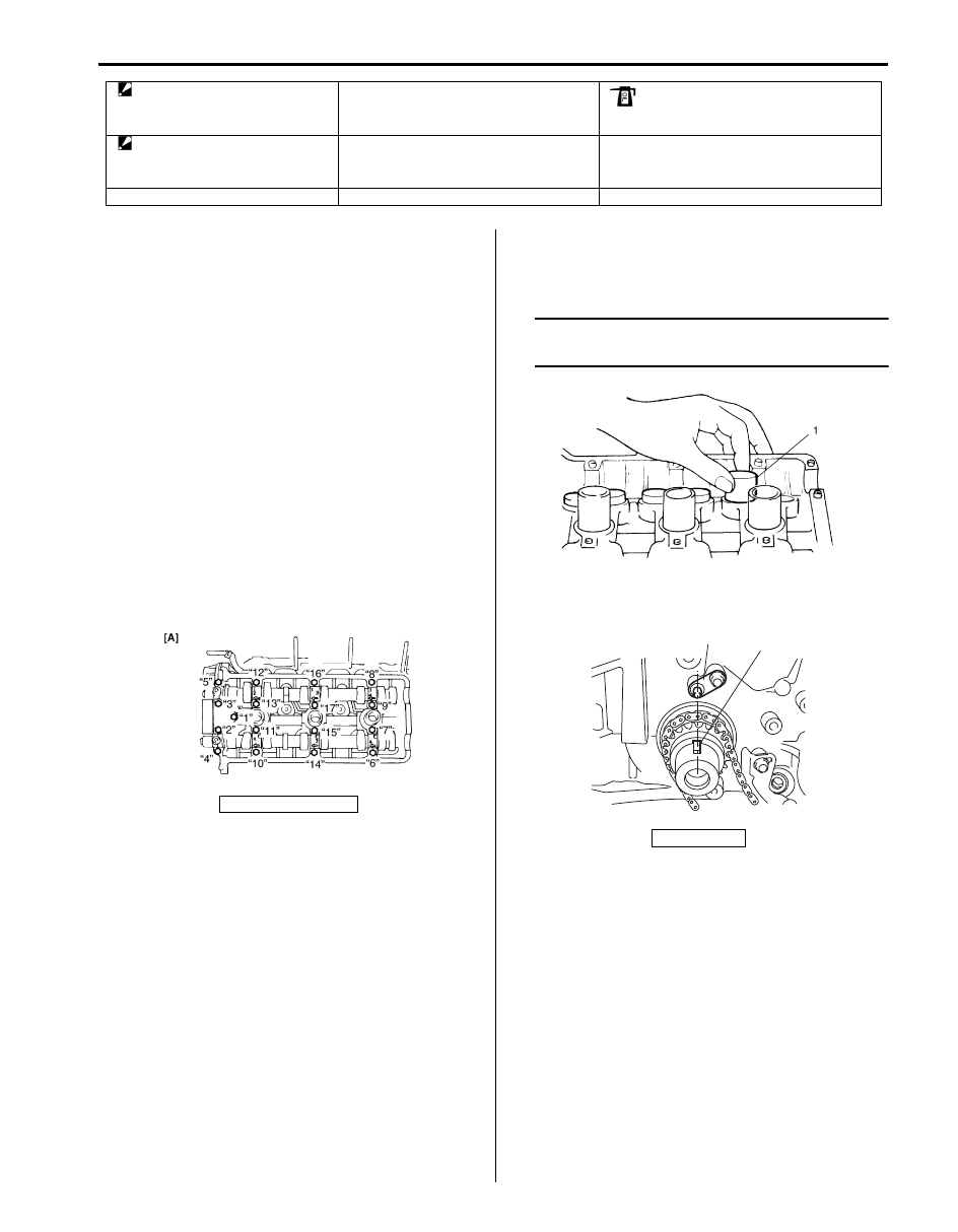
Installation
1) Apply engine oil around tappet (1), and then install
tappets with shims to cylinder head.
NOTE
When installing shim, make sure to direct
shim No. side toward tappet.
2) Check timing pulley key (1) on crankshaft as shown
in figure.
4. RH (No.2) bank exhaust camshaft
housing
: Point arrow mark on cap to camshaft
sprocket side.
10. LH (No.1) bank camshaft housing
: Apply engine oil to sliding surface of each part.
5. RH (No.2) bank intake camshaft
housing
: Point arrow mark on cap to camshaft
sprocket side.
11. Timing chain guide No.5
6. LH (No.1) bank intake camshaft
12. Tappet
[A]: LH (No.1) bank
I6JB01140078-01
2. Oil jet
I6JB01140079-01
2
1
I6JB01140080-01
Нет комментариевНе стесняйтесь поделиться с нами вашим ценным мнением.
Текст