Suzuki Grand Vitara JB627. Manual — part 386

9D-11 Wipers / Washers:
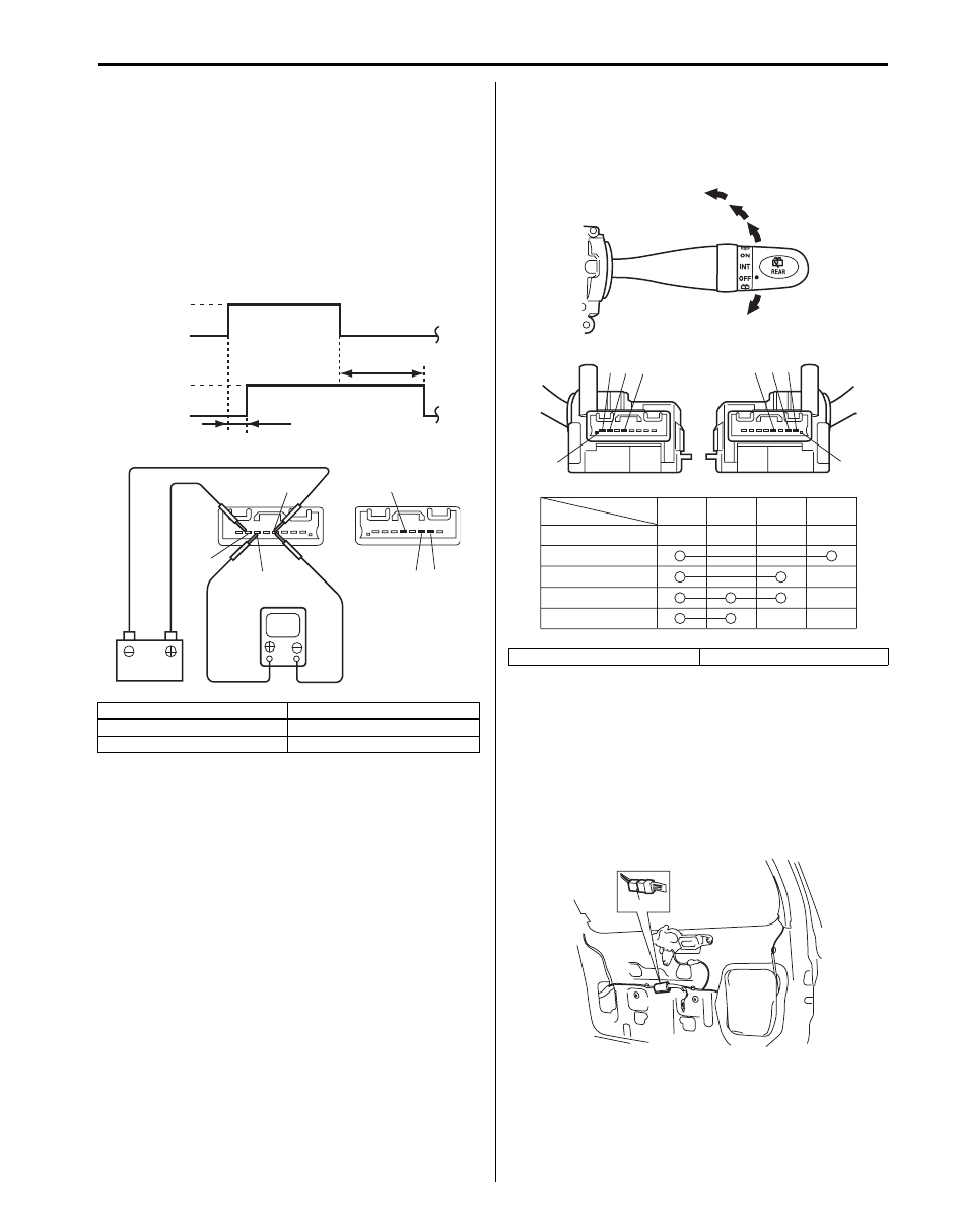
Windshield Wiper and Washer Switch
Inspection
S6JB0B9406009
Windshield Wiper and Washer Switch
Check for continuity between terminals at each switch
position. If check result is not as specified, replace
switch.
Intermittent Wiper Relay Circuit
1) Turn the windshield wiper switch to “INT” position.
2) Connect battery positive (+) terminal to terminal “5”
and its negative (–) terminal to terminal “2”.
3) Connect voltmeter positive lead to terminal “4” and
its negative lead to terminal “2”.
4) Check that the voltmeter indicates the battery
voltage (10 – 14 V).
5) Connect terminal “3” and terminal “5” by a jumper
wire.
6) Disconnect end of the jumper wire from terminal “5”.
7) Connect disconnected jumper wire end to terminal
“2”, then check that voltage between terminal “4” and
terminal “2” changes as shown.
If check result is not satisfied, replace switch.
[A]: RHD
[B]: LHD
[C]: Terminal
[D]: Wiper switch
[E]: Washer switch
OFF
INT
6
5
4
3
MIST
OFF
1
2
ON
LO
HI
6 5 4 3 2 1
1 2 3 4 5 6
[A]
[B]
[C]
[D]
[E]
[C]
I5JB0D940001-01
[A]: RHD
[B]: LHD
[A]: RHD
[D]: INT time control switch position
[B]: LHD
[E]: 1.6
± 1 sec.
[C]: Voltage
[F]: 10.7
± 5 sec.
V
2
3
4
5
2
3
4
5
[B]
[A]
I5JB0D940002-02
V
INT
TIME
INT
TIME
10-14V
0V
10-14V
0V
2
3
4
5
2
3
4
5
[B]
[A]
[C]
[D]
[E]
[F]
I5JB0D940003-02
Wipers / Washers: 9D-12
Washer Linked Circuit
1) Make sure that front wiper switch is at “OFF”
position.
2) Connect battery positive (+) terminal to terminal “5”
and its negative (–) terminal to terminal “2”.
3) Connect voltmeter positive lead to terminal “4” and
its negative lead to terminal “2”.
4) When front washer switch is ON, check that voltage
changes as shown in figure.
If check result is not satisfied, replace switch.
Rear Wiper and Washer Switch Removal and
Installation
S6JB0B9406010
For removal and installation, refer to “Windshield Wiper
and Washer Switch Removal and Installation”.
Rear Wiper and Washer Switch Inspection
S6JB0B9406011
Check for continuity between terminals at each switch
position. If check result is not as specified, replace
switch.
Rear Wiper Relay Removal and Installation
S6JB0B9406012
Removal
1) Disconnect negative (–) cable at battery.
2) Remove rear end door trim from rear end door
referring to “Rear End Door Lock Assembly Removal
and Installation in Section 9F”.
3) Remove rear wiper relay (1).
Installation
Reverse removal procedure for installation.
[A]: RHD
[D]: Voltage
[B]: LHD
[E]: Approx. 2.2 sec.
[C]: Wiper switch
[F]: Approx. 0.3 sec.
V
2
4
5
2
4
5
[B]
[A]
ON
OFF
High
Low
[E]
[F]
[C]
[D]
I5JB0D940004-02
[A]: RHD
[B]: LHD
OFF
[C]
[D]
4
3
1
2
1
2
3
4
[A]
[B]
1
2 3
4
[C]
[D]
[E]
[F]
[E]
[F]
I5JB0D940005-01
1
I5JB0A940021-01
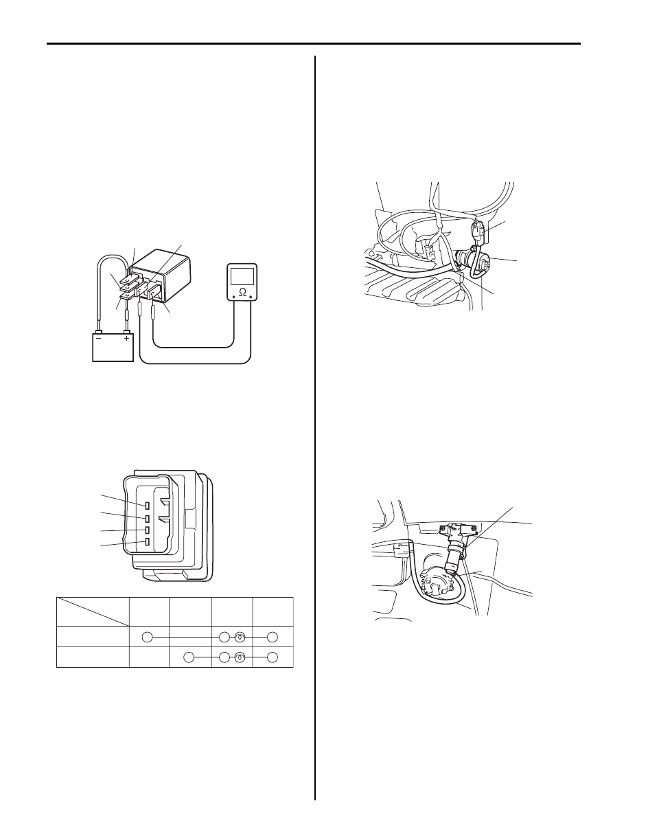
9D-13 Wipers / Washers:
Rear Wiper Relay Inspection
S6JB0B9406013
1) Check that there is no continuity between terminal
“4” and “5”. If there is continuity, replace relay.
2) Check that there is continuity between terminal “3”
and “5”. If there is no continuity, replace relay.
3) Connect battery positive (+) terminal to terminal “2”
of relay.
4) Connect battery negative (–) terminal to terminal “1”
of relay.
5) Check continuity between terminal “4” and “5”. If
there is no continuity when relay is connected to the
battery, replace relay.
Headlight Washer Switch Inspection (If
Equipped)
S6JB0B9406014
Check for continuity between terminals at each switch
position.
If check result is not as specified, replace switch.
Headlight Washer Pump Removal and
Installation (If Equipped)
S6JB0B9406015
Removal
1) Remove front bumper referring to “Front Bumper
2) Disconnect headlight washer hose (1) and washer
pump connector (2) from headlight washer pump (3).
3) Remove headlight washer pump from washer tank.
Installation
Reverse removal procedure for installation.
Headlight Washer Nozzle Removal and
Installation (If Equipped)
S6JB0B9406016
Removal
1) Remove front bumper referring to “Front Bumper
2) Disconnect headlight washer hose (1) from headlight
washer nozzle (2).
3) Remove headlight washer nozzle from front bumper.
Installation
Reverse removal procedure for installation.
“5”
“2”
“1”
“4”
“3”
I5JB0A940022-01
1
2
3
4
Switch Position
Terminal
ON (PUSH IN)
1
2
3
4
OFF
I5JB0A940023-01
1
2
3
I5JB0A940024-01
2
1
I5JB0A940025-01

Wipers / Washers: 9D-14
Specifications
Tightening Torque Specifications
S6JB0B9407001
NOTE
The specified tightening torque is also described in the following.
“Wipers and Washers Components”
Reference:
For the tightening torque of fastener not specified in this section, refer to “Fastener Information in Section 0A”.
Fastening part
Tightening torque
Note
N
⋅m
kgf-m
lb-ft
Windshield wiper bolt
8.5
0.85
6.5
Windshield wiper arm nut
14
1.4
10.5
Rear wiper motor mounting bolt
7
0.7
5.0
Rear wiper arm nut
8
0.8
6.0
Нет комментариевНе стесняйтесь поделиться с нами вашим ценным мнением.
Текст