Suzuki Grand Vitara JB627. Manual — part 328
9A-6 Wiring Systems:
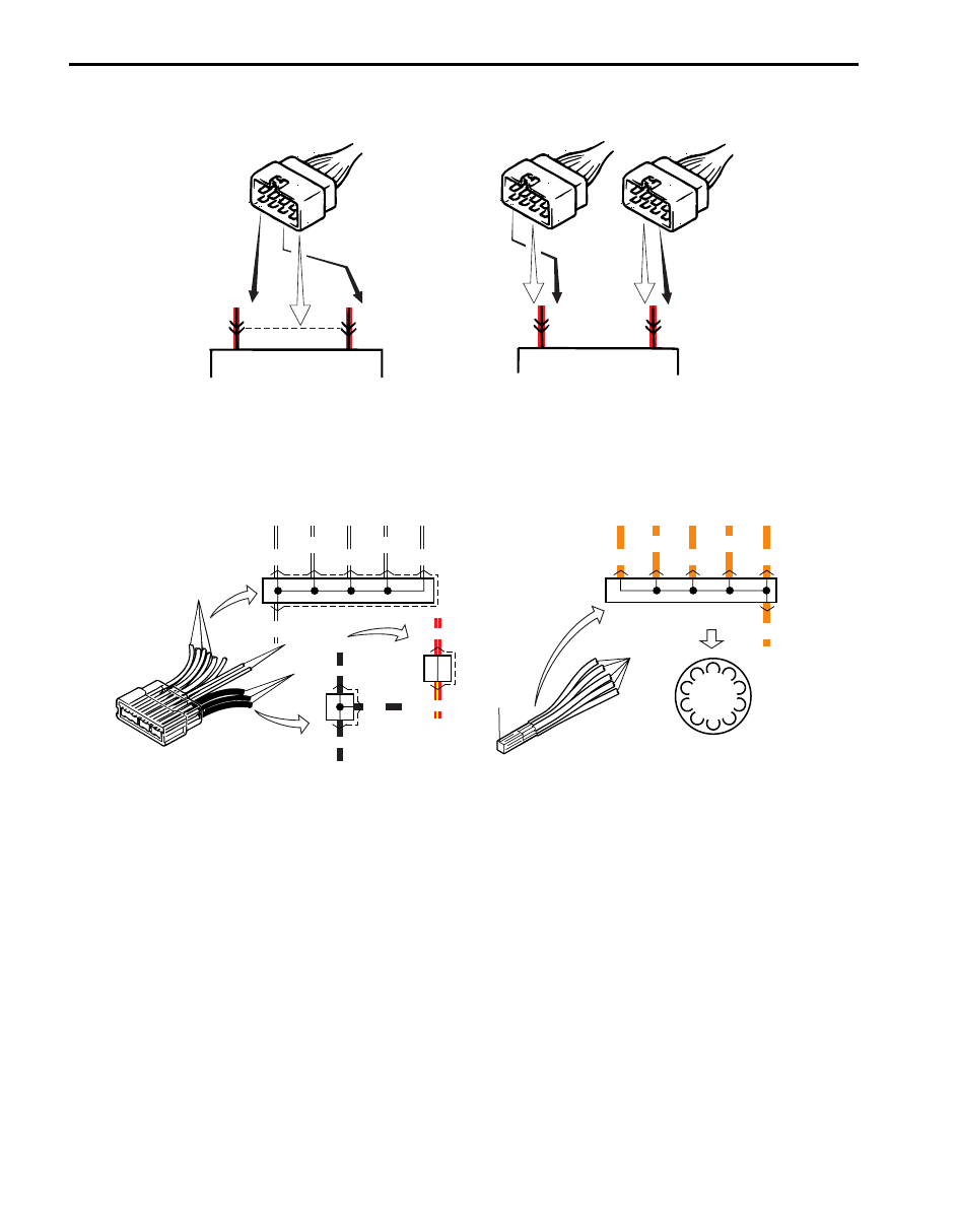
3) Terminals in one connector (Broken line) (B15)/Terminals in different connectors (B14, B16)
4) Joint connector (J/C)
• The joint connector (J/C) connects several different wires with the same wire color at one place instead of
connecting them by welding or caulking one by one. It is not an ordinary connector but a part of the continuous
wire in the harness.
B15
B15
B14
B16
5
7
B14
B16
5
7
I2RH01910904-01
BLK
BLK
A
A
A
B
B
RED/YEL
Weld
ORN
WHT/BLK
J/C
Weld splice
BLK
BLK
RED/YEL
RED/YEL
WHT/BLK
WHT/BLK
WHT/BLK
WHT/BLK
WHT/BLK
WHT/BLK
C
C
C
C
C
C
Weld
splice
(in Connector list)
J/C
ORN
ORN
ORN
ORN
ORN
ORN
Weld
splice
Example
I4RS0A910902-01
Wiring Systems: 9A-7
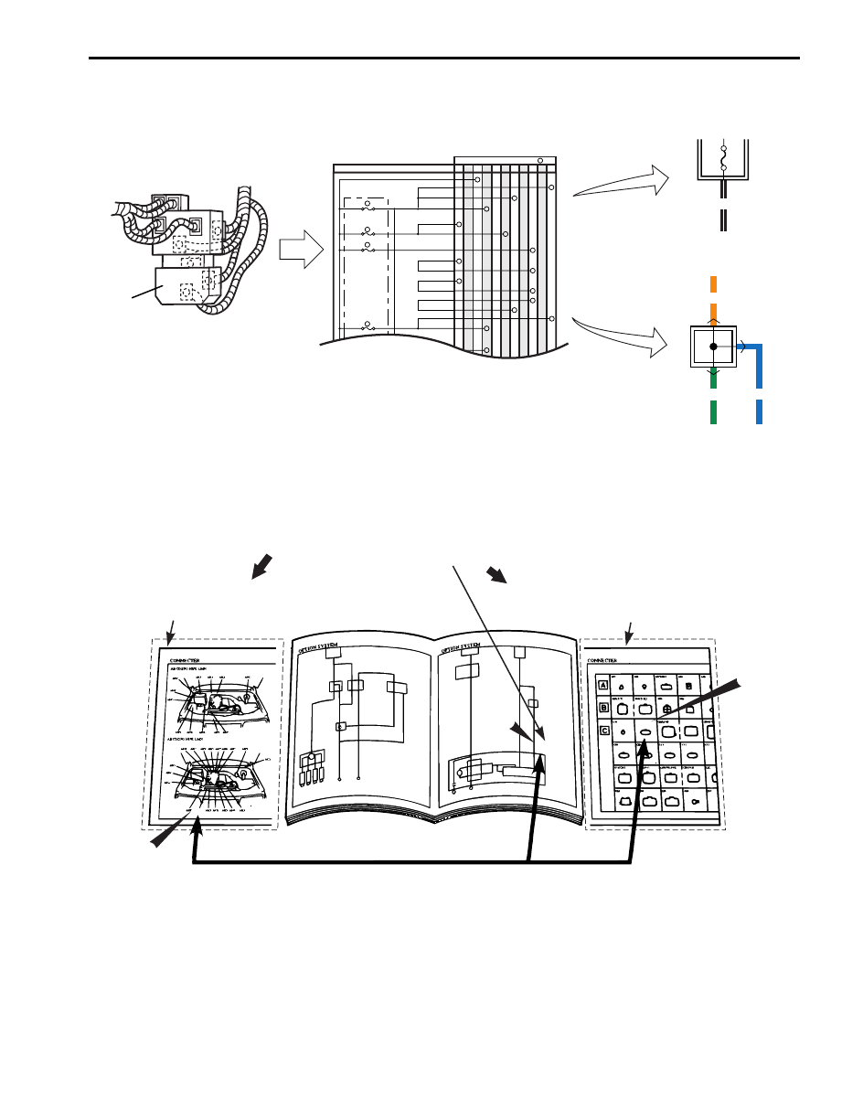
5) Junction block (J/B)
6) Connector location, shape and terminal No.
Refer to “Connector Layout Diagram”.
Refer to “System Circuit Diagram”.
Refer to “List of Connectors”.
IMMOBI IG
IG1
IG Coil, etc
E39
E41
E40
BCM
G34
G33
G32
K01 L04
L05
L06
IG Coil
IG1
15A
MTR
10A
A/B
15A
2
6
5
13
J/B
Connector No. / Terminal No.
BCM ;IG1
MTR Power, etc
A/B CONT
K-LINE
K-LINE
A/B SIGNAL
A/B SIGNAL
A/B SIG
A/B SIG
IG Sig
10A
EPS AT
MTA
4
6
1
3
2
4
8
11
9
12
9
11
23
25
30
29
Example
J/B
BLK/WHT
J/B
ORN
GRN
BLU
J/B
J/B inner circuit
I4RS0A910903-01
"SYSTEM CIRCUIT DIAGRAM"
-Connector code and terminal No.
"CONNECTOR LAYOUT DIAGRAM"
-Connector location.
CROSS-REFERENCE
"CONNECTOR LIST"
-Connector shape and terminal position.
C02
C02
C02
C02
C02
C02
I2RH01910906-01
9A-8 Wiring Systems:
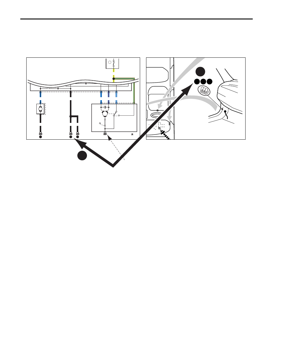
How to Read Ground Point
S6JB0B9101006
Refer to “System Circuit Diagram”.
Refer to “Ground (earth) Point”.
Left side shown
10 11 12
"SYSTEM CIRCUIT DIAGRAM"
"GROUND POINT"
CROSS-REFERENCE
Windoshield
washer
motor
Individual
circuit
fuse box
20
15A
Windoshield
wiper
motor
E40
E09
E20
16
2
1
Off
On
Circuit
breaker
60A-B003-
YEL/BLU
1
20
5
2
1
3
4
6
7
BLU/BLK
BLK
10
BLK
BLK
9
10
10
BLK
M
BLU
BLU/WHT
BLU/RED
M
Device body grounding is not given the ground point number.
I4JA01910985-01
Wiring Systems: 9A-9
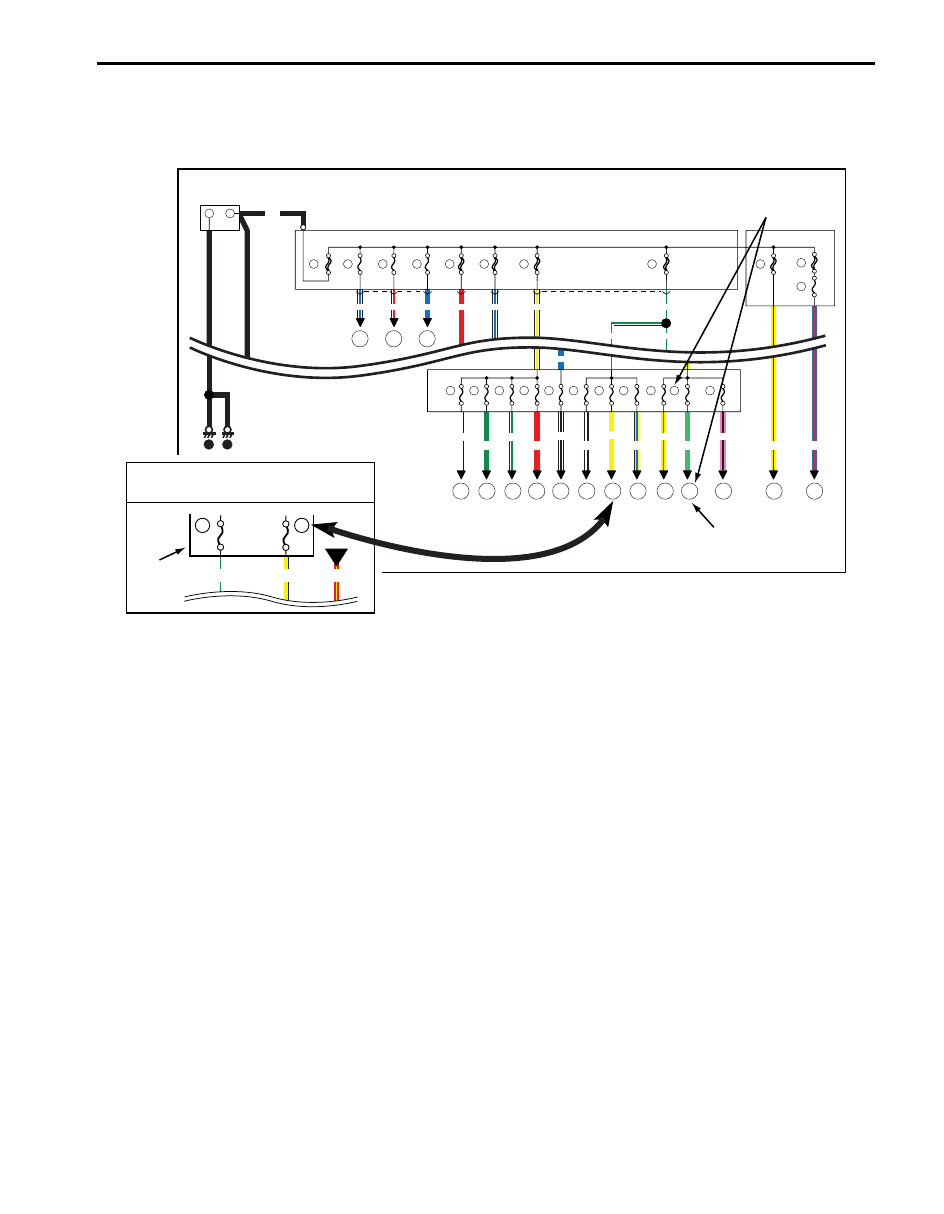
How to Read Power Supply Diagram
S6JB0B9101007
Refer to “Power Supply Diagram”.
Refer to “System Circuit Diagram”.
Connection to the system
indicated.
"POWER SUPPLY DIAGRAM"
-
+
1
Battery
80A
2
15A
3
15A
4
15A
5
25A
6
7
8
50A
30A
29
30A
32
15A
9
60A
60A
BLK
YEL/BLK
PNK/BLK
LT GRN
YEL/GRN
YEL/BLU
BLK/WHT
WHT/BLK
WHT/GRN
RED
GRN
WHT
WHT/BLU WHT/RED
WHT/BLU
WHT/YEL
WHT/GRN
WHT/GRN
WHT/GRN
BLU
BLU/RED
RED
YEL
BLU/RED
Individual
circuit
fuse box
Main fuse box
Supplementary fuse box
11
11
2
4
3
12 13 14 15 16 17 18
19 20
21
29
32
12
13
14
15
16
17
18
19
20
21
15A
15A
15A
20A
20A
15A
15A
15A
15A
15A
15A
E44
3
2
1
B01
1
E45
1
E40
2
1
Fuse
RED/YEL
YEL
WHT/GRN
15A
15A
13
17
"SYSTEM CIRCUIT DIAGRAM"
Fuse number
1
2
RY
I4JA01910986-01
Нет комментариевНе стесняйтесь поделиться с нами вашим ценным мнением.
Текст