Suzuki Grand Vitara JB627. Manual — part 262
6C-9 Power Assisted Steering System:
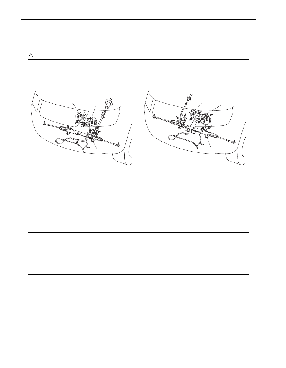
P/S Fluid Leakage Check
S6JB0B6306003
Start engine and turn steering wheel fully to the right and left so that maximum hydraulic pressure is provided.
Then visually check P/S gear case assembly (1), P/S pump (2) and P/S fluid reservoir (3) themselves and each joint of
their connecting pipes for leakage.
CAUTION
!
Never keep steering wheel turned fully for longer than 10 seconds.
P/S System Air Bleeding Procedure
S6JB0B6306004
1) Hoist the front end of vehicle and apply safety stands.
2) Fill P/S fluid reservoir with fluid up to specified level.
NOTE
Before starting engine, place transmission gear shift lever in “Neutral” (shift selector lever to “P”
range for A/T model), and set parking brake.
3) After running engine at idling speed for 3 to 5 seconds, stop it and add fluid to satisfy specification.
4) With engine stopped, turn steering wheel to the right and left as far as it stops, repeat it a few times and fill fluid to
specified level.
5) With engine running at idling speed, repeat stop-to-stop turn of steering wheel till all foams in P/S fluid reservoir
are gone.
NOTE
Make sure to bleed air completely. If air remains in fluid, P/S pump may make humming noise or
steering wheel may feel heavy.
6) Finally check to make sure that fluid is filled to specified level.
3
2
1
3
2
1
[B]
[A]
I6JB0B630004-01
[A]: LHD model
[B]: RHD model
Power Assisted Steering System: 6C-10
P/S Pump and A/C Compressor (If Equipped)
Drive Belt Inspection and Adjustment
S6JB0B6306005
Inspection
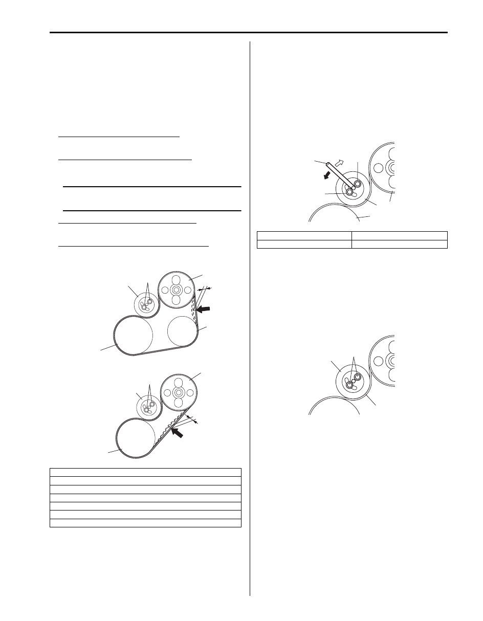
• Check that belt is free from any damage and properly
fitted in pulley groove.
• Check belt tension by measuring how much it deflects
when pushed at intermediate point between pulleys
with about 10 kg (22 lb) force.
Deflection of P/S belt with A/C (a)
: 5.5 – 6.5 mm (0.21 – 0.25 in.)
Deflection of P/S belt without A/C (b)
: 4 – 9 mm (0.16 – 0.35 in.)
NOTE
When replacing drive belt, adjust drive belt
tension to the following specifications.
Deflection of new P/S belt with A/C (a)
: 5 – 6 mm (0.19 – 0.23 in.)
Deflection of new P/S belt without A/C (b)
: 4 – 9 mm (0.16 – 0.35 in.)
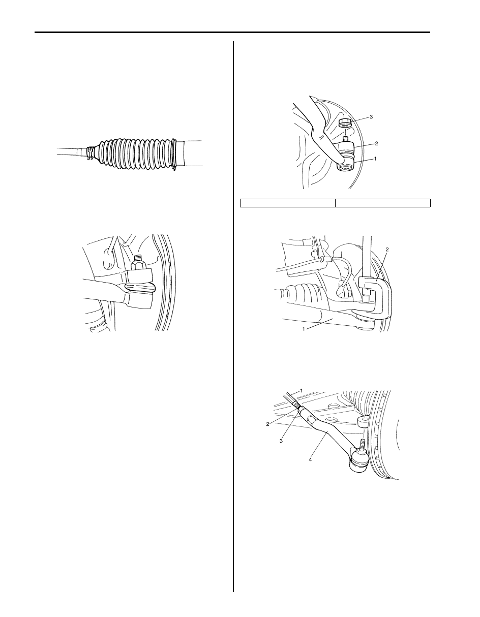
Adjustment
1) To adjust P/S belt tension, loosen tension pulley
bolts (1) and turn tension pulley (2) using hexagon
wrench (3).
2) Adjust belt tension to specification, and then tighten
tension pulley bolts (1) to specified torque.
Tightening torque
P/S belt tension pulley bolt (a): 25 N·m (2.5 kgf-
m, 18.5 lb-ft)
P/S Pump and A/C Compressor (If Equipped)
Drive Belt Removal and Installation
S6JB0B6306006
Removal
1) Remove tension pulley bolts (1).
2) Remove tension pulley (3) and P/S pump drive belt
(2).
Installation
Reverse removal procedure noting the following
instruction.
Adjust belt tension referring to “P/S Pump and A/C
Compressor (If Equipped) Drive Belt Inspection and
Adjustment”.
1. P/S pump pulley
2. A/C compressor pulley (if equipped)
3. Crankshaft pulley
4. Tension pulley
5. Tension pulley bolt
[A]: with A/C
[B]: without A/C
4
5
4
3
3
2
1
1
[A]
[B]
“a”
“b”
5
I5JB0C630001-01
4. Crank shaft pulley
6. Tight
5. Loose
7. P/S pump pulley
3
4
2
7
6
1, (a)
1, (a)
5
I6JB0B630005-01
3
2
1
I6JB01630005-01
6C-11 Power Assisted Steering System:
Steering Rack Boot Check
S6JB0B6306007
• Check boot for crack and damage which, if any,
means possibility of rusty gear, entry of dust or lack of
grease. Also, check if any of such faulty conditions
exists.
• Check steering rack boot for dent or breakage.
If there is a dent, keep boot in most compressed state
for some seconds to correct dent.
Tie-Rod End Boot Check
S6JB0B6306008
Check boot for crack and damage and if any, replace it
with a new one.
Tie-Rod End Removal and Installation
S6JB0B6306009
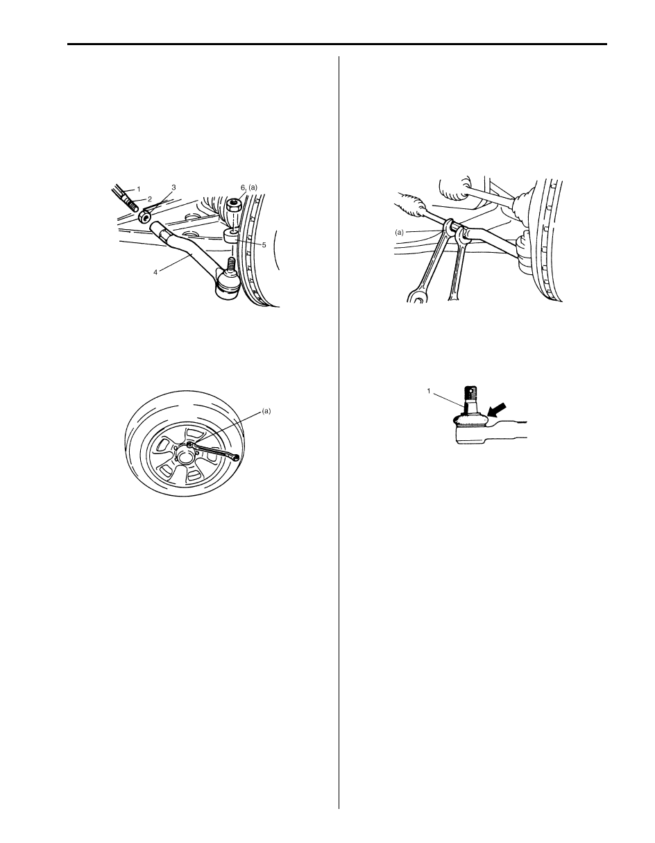
Removal
1) Hoist vehicle and remove wheel.
2) Remove tie-rod end nut (3).
3) Disconnect tie-rod end (1) by using puller (2).
4) To facilitate adjustment after installation, put a mark
(2) on tie-rod thread indicating position of tie-rod end
lock nut (3). Then loosen lock nut (3) and remove tie-
rod end (4) from tie-rod (1).
IYSQ01630013-01
IYSQ01630014-01
1. Tie-rod end
2. Knuckle
IYSQ01630015-01
IYSQ01630016-01
IYSQ01630017-01
Power Assisted Steering System: 6C-12
Installation
1) Install tie-rod end lock nut (3) and tie-rod end (4) to
tie-rod (1). Tighten lock nut (3) to mark (2) on tie-rod
thread.
2) Install tie-rod end (4) to knuckle (5). Tighten new tie-
rod end nut (6) to specified torque.
Tightening torque
Tie-rod end nut (a): 43 N·m (4.3 kgf-m, 31.0 lb-ft)
3) After installing wheels, lower vehicle and tighten
wheel nuts to specified torque.
Tightening torque
Wheel nut (a): 100 N·m (10.0 kgf-m, 72.5 lb-ft)
4) Check that proper amount of toe-in is obtained
referring to “Front Wheel Alignment Inspection and
Adjustment in Section 2B”.
5) After confirming proper amount of toe-in, tighten tie-
rod end lock nut to specified torque.
Tightening torque
Tie-rod end lock nut (a): 65 N·m (6.5 kgf-m, 47.0
lb-ft)
Tie-Rod End Ball Joint Inspection
S6JB0B6306010
Inspect for play in tie-rod end ball joint (1). If found
defective, replace.
IYSQ01630018-01
IYSQ01630019-01
IYSQ01630020-01
IYSQ01630021-01
Нет комментариевНе стесняйтесь поделиться с нами вашим ценным мнением.
Текст