Suzuki Grand Vitara JB627. Manual — part 205
5A-4 Automatic Transmission/Transaxle:
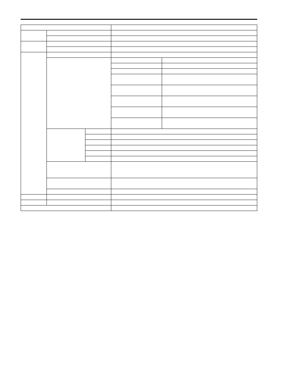
Item
Specifications
Torque
converter
Type
3-element, 1-step, 2-phase type (with TCC (lock-up) mechanism)
Stall torque ratio
1.75
Oil pump
Type
Trochoid type oil pump
Drive system
Engine driven
Gear
change
device
Type
Forward 5-step, reverse 1-step planetary gear type
Shift position
“P” range
Gear in neutral, output shaft fixed, engine start
“R” range
Reverse
“N” range
Gear in neutral, engine start
“D” range (Transfer 4H) Forward 1st
↔ 2nd ↔ 3rd ↔ 4th ↔ 5th
automatic gear change
“4” range (Transfer 4H) Forward 1st
↔ 2nd ↔ 3rd ↔ 4th automatic
gear change
“D” range (Transfer 4L) Forward 1st
↔ 2nd ↔ 3rd ↔ 4th automatic
gear change
“3” range
Forward 1st
↔ 2nd ↔ 3rd ← 4th ← 5th
automatic gear change
“L” range
Forward 1st
← 2nd ← 3rd ← 4th ← 5th
reduction, and fixed at 1st gear
Gear ratio
1st
3.520
2nd
2.043
3rd
1.401
4th
1.000
5th
0.717
Reverse
3.224
Control elements
Wet type multi-disc clutch ... 3 sets
Wet type multi-disc brake ... 4 sets
One-way clutch ... 3 sets
Transfer
Hi: 1.000
Lo: 1.970
Final gear reduction ratio
4.300
Lubrication Lubrication system
Forced feed system by oil pump
Cooling
Cooling system
Radiator assisted cooling (water-cooled)
Fluid used
SUZUKI ATF 3317 or Mobil ATF 3309
Automatic Transmission/Transaxle: 5A-5
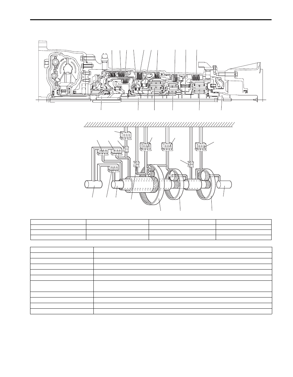
Clutch / Brake Functions of Automatic Transmission
S6JB0B5101002
1
1
2
2
3
3
4
4
5
5
6
6
7
7
8
8
9
9
10
10
11
11
12
12
13
13
14
14
15
15
16
16
I6JB01510004-01
1. Forward clutch
5. No.2 brake
9. One-way No.2 clutch
13. Output shaft
2. Direct clutch
6. 2nd brake
10. One-way No.3 clutch
14. FR planetary
3. Reverse clutch
7. 1st and reverse brake
11. Input shaft
15. MD planetary
4. No.1 brake
8. One-way No.1 clutch
12. Intermediate shaft
16. RR planetary
Part Name
Function
Forward clutch
Meshes input shaft and intermediate shaft.
Direct clutch
Meshes input shaft and MD planetary carrier.
Reverse clutch
Meshes input shaft and FR sun gear.
No.1 brake
Fixes FR planetary carrier.
No.2 brake
Fixes FR and MD ring gear.
2nd brake
Fixes outer race of one-way No.2 clutch, to prevent FR sun gear from turning
counterclockwise (reverse direction of engine input rotation direction).
1st and reverse brake
Fixes RR ring gear.
One-way No.1
Prevent FR planetary carrier from turning counterclockwise.
One-way No.2
Prevent FR sun gear from turning counterclockwise only when 2nd brake is at work.
One-way No.3
Prevent RR ring gear from turning counterclockwise.
5A-6 Automatic Transmission/Transaxle:
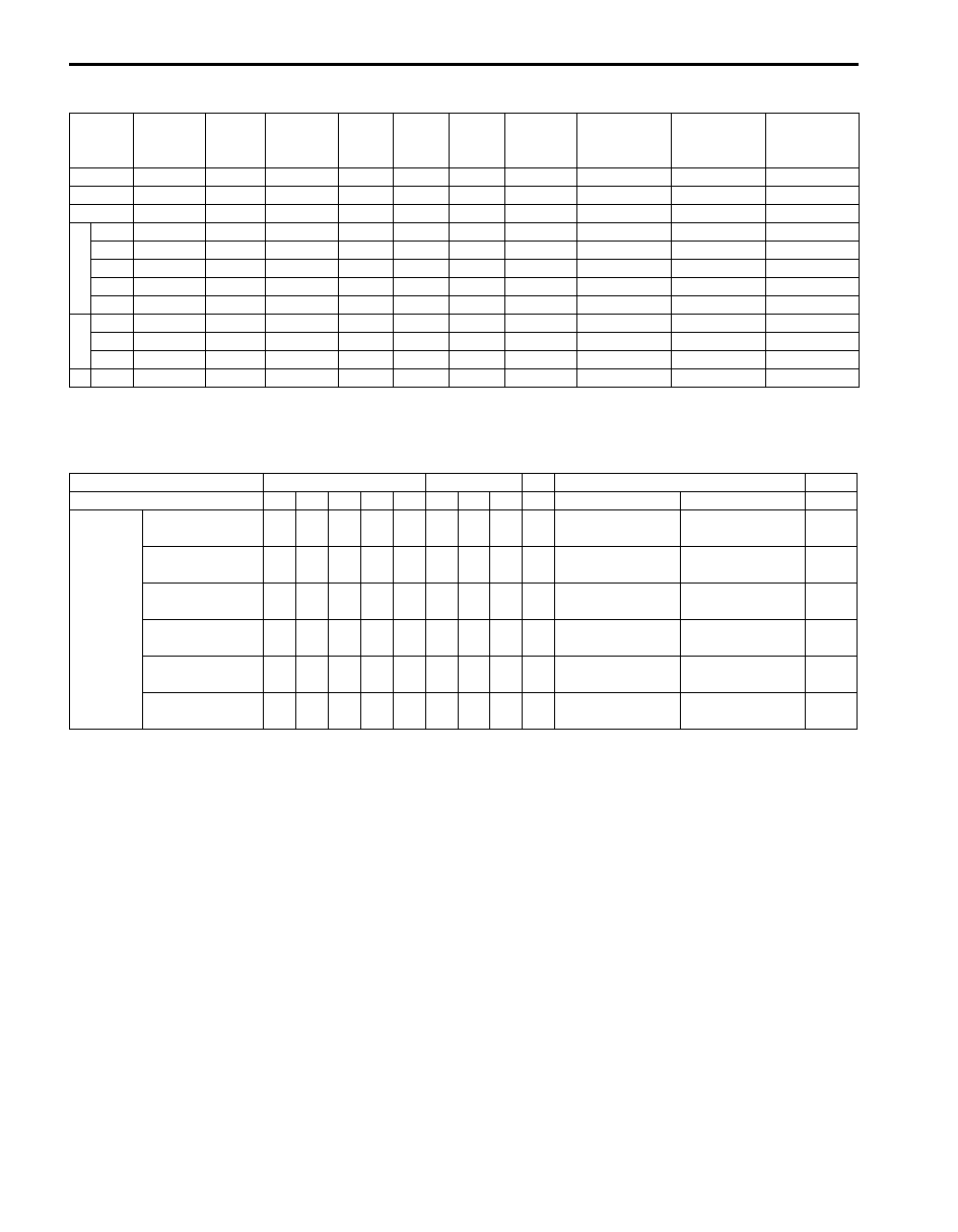
Table of A/T Component Operation
S6JB0B5101003
{
: Operating
Operation of Shift Solenoids and TCC Solenoid
S6JB0B5101009
{
: ON (Turn power on)
X: OFF (Turn power off)
Forward
clutch
Direct
clutch
Reverse
clutch
No.1
brake
No.2
brake
2nd
brake
1st and
Reverse
brake
One-way
No.1 clutch
One-way
No.2 clutch
One-way
No.3 clutch
P
—
—
—
—
—
—
—
—
—
—
R
—
—
{
{
—
—
{
{
—
—
N
—
—
—
—
—
—
—
—
—
—
D
1st
{
—
—
—
—
—
—
—
—
{
2nd
{
—
—
—
—
{
—
{
{
—
3rd
{
—
{
—
—
{
—
{
—
—
4th
{
{
{
—
—
{
—
—
—
—
5th
—
{
{
{
—
{
—
—
—
—
3
1st
{
—
—
—
—
—
—
—
—
{
2nd
{
—
—
—
—
{
—
{
{
—
3rd
{
—
{
{
—
{
—
—
—
—
L 1st
{
—
—
—
—
—
{
—
—
—
Range
D
3
L
R
P & N
Gear
1st 2nd 3rd 4th 5th 1st 2nd 3rd 1st Rev (
≥ 11 km/h) Rev (< 11 km/h)
—
Solenoids
Shift solenoid
valve-A
{
{
X
X
X
{
{
X
{
X
{
{
Shift solenoid
valve-B
X
{
{
X
X
X
{
{
X
{
X
X
Shift solenoid
valve-E
X
X
X
X
{
X
X
X
X
X
X
X
Pressure control
solenoid valve-B
X
X
X
X
{
X
X
X
X
X
X
X
Pressure control
solenoid valve-C
{
{
{
{
X
{
{
X
X
{
{
{
TCC solenoid
valve
X
X
X ({) ({) X
X
X
X
X
X
X
Automatic Transmission/Transaxle: 5A-7
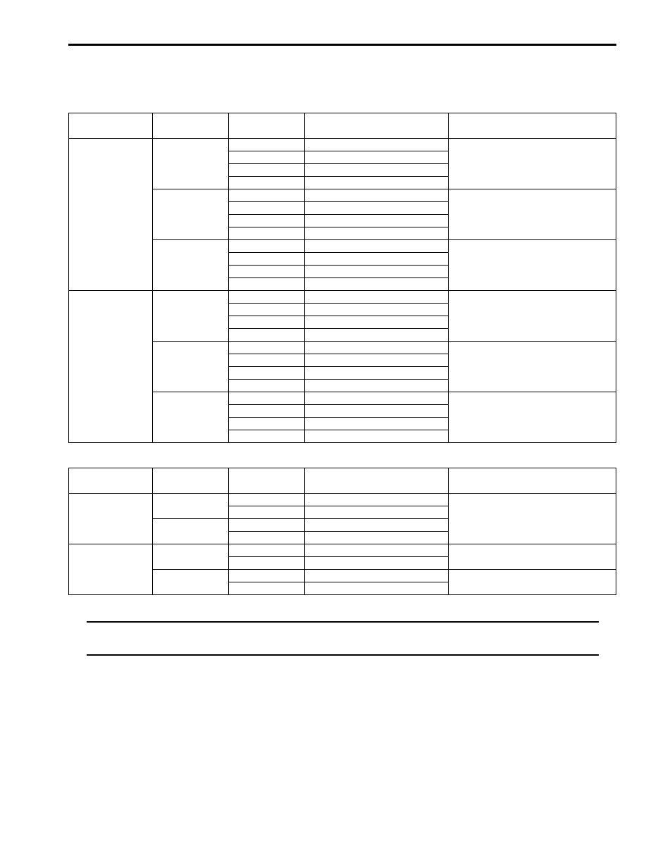
Automatic Gear Shift Table
S6JB0B5101010
Automatic gear shift schedule is shown in the following table. Test-drive the vehicle on a flat road in the D position.
1. Shift Point in D position and transfer shift position in 4H
2. TCC lock-up point in D position and/or 4 position mode
NOTE
The gear change is done at the shift point different from the above while any of the following control
functions is working. Bear this in mind when performing inspection.
• Slope Shift Control
When TCM makes up-slope judgment, Slope Shift Control (on up-slope) is executed by changing the gear change
point to the high-speed side so as to reduce frequent up-shift and down-shift operations.
When TCM makes down-shift judgment, Slope Shift Control (on down-slope) is executed by changing the gear
change point to the low-speed side so as to use engine-brake function effectively while driving on a down-slope.
• Cruise Shift Control
Cruise Shift Control is executed by selecting appropriate gear according to requirement for retaining a constant
vehicle speed or acceleration so as to reduce frequent up-shift and down-shift operations while cruising.
Throttle
opening (%)
Shift
Vehicle speed km/h (mph)
Remark
UP shift
Over 90%
1st
→ 2nd
45 – 50 (28 – 31)
2nd
→ 3rd
85 – 90 (53 – 56)
3rd
→ 4th
132 – 137 (82 – 85)
4th
→ 5th
177 – 182 (110 – 113)
50%
1st
→ 2nd
24 – 29 (15 – 18)
2nd
→ 3rd
52 – 57 (32 – 35)
3rd
→ 4th
77 – 82 (48 – 51)
4th
→ 5th
143 – 148 (89 – 92)
10%
1st
→ 2nd
10 – 15 (6 – 9)
2nd
→ 3rd
17 – 22 (11 – 14)
3rd
→ 4th
33 – 38 (21 – 24)
4th
→ 5th
48 – 53 (30 – 33)
DOWN shift
Over 90%
5th
→ 4th
167 – 172 (104 – 107)
4th
→ 3rd
122 – 127 (76 – 79)
3rd
→ 2nd
45 – 50 (28 – 31)
2nd
→ 1st
30 – 35 (19 – 22)
50%
5th
→ 4th
68 – 73 (42 – 45)
4th
→ 3rd
43 – 48 (27 – 30)
3rd
→ 2nd
18 – 23 (11 – 14)
2nd
→ 1st
6 – 11 (4 – 7)
0%
5th
→ 4th
20 – 25 (12 – 16)
With applying brake pedal (coast
down condition)
4th
→ 3rd
17 – 22 (11 – 14)
3rd
→ 2nd
7 – 12 (4 – 7)
2nd
→ 1st
3 – 8 (2 – 5)
TCC status
Throttle
opening (%)
Vehicle speed km/h (mph)
Remark
4
th
gear lock-up
ON
50%
152 – 157 (94 – 98)
With “4” range condition
20 – 30%
53 – 67 (33 – 41)
OFF
50%
70 – 75 (44 – 47)
20 – 30%
44 – 49 (27 – 30)
5
th
gear lock-up
ON
50%
174 – 179 (108 – 111)
20 – 30%
71 – 90 (44 – 56)
OFF
50%
147 – 152 (91 – 94)
20 – 30%
62 – 67 (39 – 42)
Нет комментариевНе стесняйтесь поделиться с нами вашим ценным мнением.
Текст