Suzuki Grand Vitara JB416 / JB420. Manual — part 124
1F-12 Engine Cooling System:
Radiator Removal and Installation
S5JB0A1606014
Removal
1) Disconnect negative cable at battery.
2) For A/T, drain A/T fluid referring to “A/T Fluid Change
3) Drain coolant.
4) Remove cooling fan assembly referring to “Radiator
Cooling Fan Assembly Removal and Installation”.
5) For A/T, remove A/T fluid cooler inlet and outlet
hoses.
6) Remove radiator outlet hose from radiator.
7) Remove condenser bolts from condenser brackets.
8) Remove radiator from vehicle.
Installation
Reverse removal procedures, noting the following.
• Refill cooling system referring to Step 7) to 17) of
“Cooling System Flush and Refill”.
• After installation, verify there is no coolant leakage
each connection.
• Refill A/T fluid referring to “A/T Fluid Change in
Water Pump Removal and Installation (For M16
Engine Model)
S5JB0A1606017
Removal
1) Disconnect negative cable at battery.
2) Drain coolant.
3) Remove water pump and generator drive belt
referring to “Water Pump and Generator Drive Belt
Removal and Installation (For M16 Engine) in
Section 1J”.
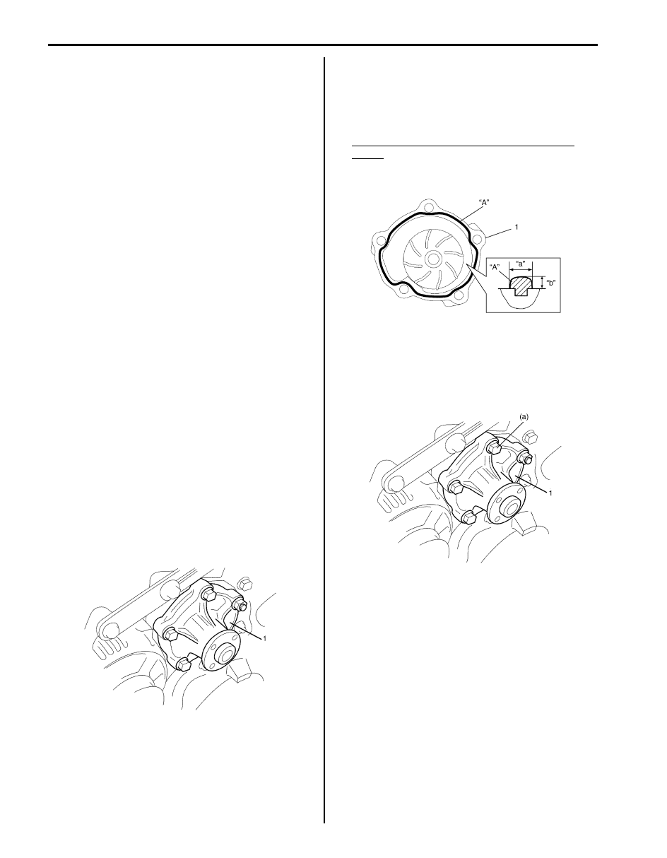
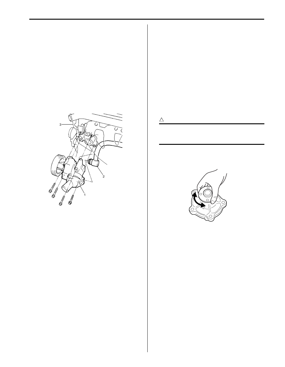
4) Remove water pump assembly (1).
Installation
1) Apply sealant to mating surface of water pump (1) as
shown in the figure.
“A”: Water tight sealant 99000–31250 (SUZUKI
Bond No.1207F)
Sealant quantity (to mating surface of water
pump)
Width “a”: 3 mm (0.12 in.)
Height “b”: 2 mm (0.08 in.)
2) Install water pump assembly (1) to cylinder block
and tighten bolts and nut to specified torque.
Tightening torque
Water pump bolt and nut (a): 25 N·m (2.5 kgf-m,
18.0 lb-ft)
3) Install water pump pulley.
4) Install water pump and generator drive belt referring
to “Water Pump and Generator Drive Belt Removal
and Installation (For M16 Engine) in Section 1J”.
5) Install P/S pump and A/C compressor drive belt (if
equipped) referring to “P/S Pump and A/C
Compressor (If Equipped) Drive Belt Removal and
Installation for M16 Engine Model in Section 6C”.
6) Refill cooling system referring to Step 7) to 17) of
“Cooling System Flush and Refill”.
7) Connect negative cable at battery.
8) Check each part for leakage.
I2RH0B160016-01
I3RM0A160016-01
I2RH0B160018-01
Engine Cooling System: 1F-13
Water Pump Removal and Installation (For J20
Engine Model)
S5JB0A1606023
Removal
1) Disconnect negative cable at battery.
2) Drain coolant referring to “Cooling System Draining”.
3) Remove water pump and generator drive belt
referring to “Water Pump and Generator Drive Belt
Removal and Installation (For J20 Engine) in Section
1J”.
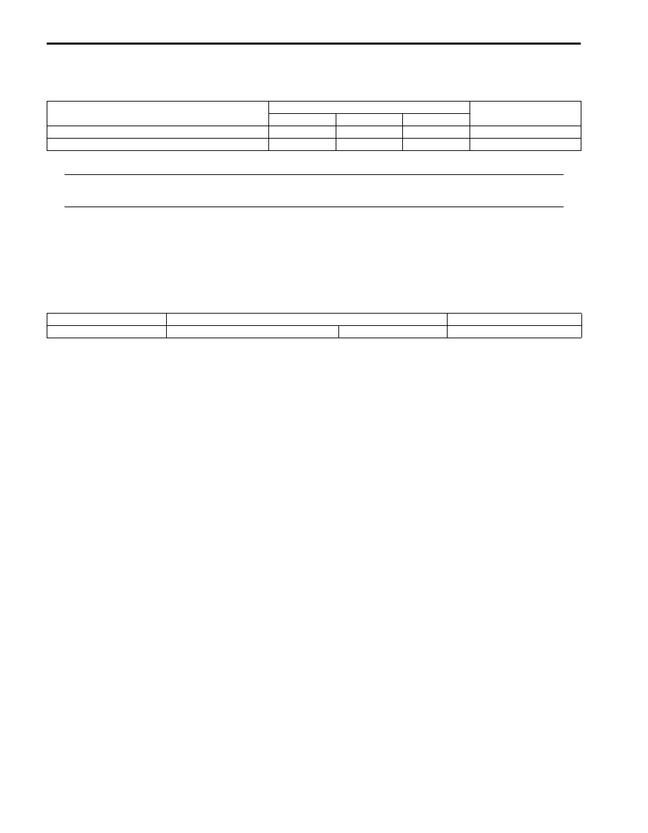
4) Remove thermostat referring to “Thermostat
Removal and Installation (For J20 Engine Model)”.
5) Disconnect heater pipe (2) from water pump (1).
6) Remove water pump (1) from cylinder block (3).
Installation
Reverse removal procedure for installation noting the
following points.
• Use new O-ring when installing.
• Install water pump assembly to cylinder block and
tighten bolts to specified torque.
Tightening torque
Water pump bolt: 25 N·m (2.5 kgf-m, 18.0 lb-ft)
• Refill cooling system referring to Step 7) to 17) of
“Cooling System Flush and Refill”.
• Verify that there is no coolant leakage at each
connection.
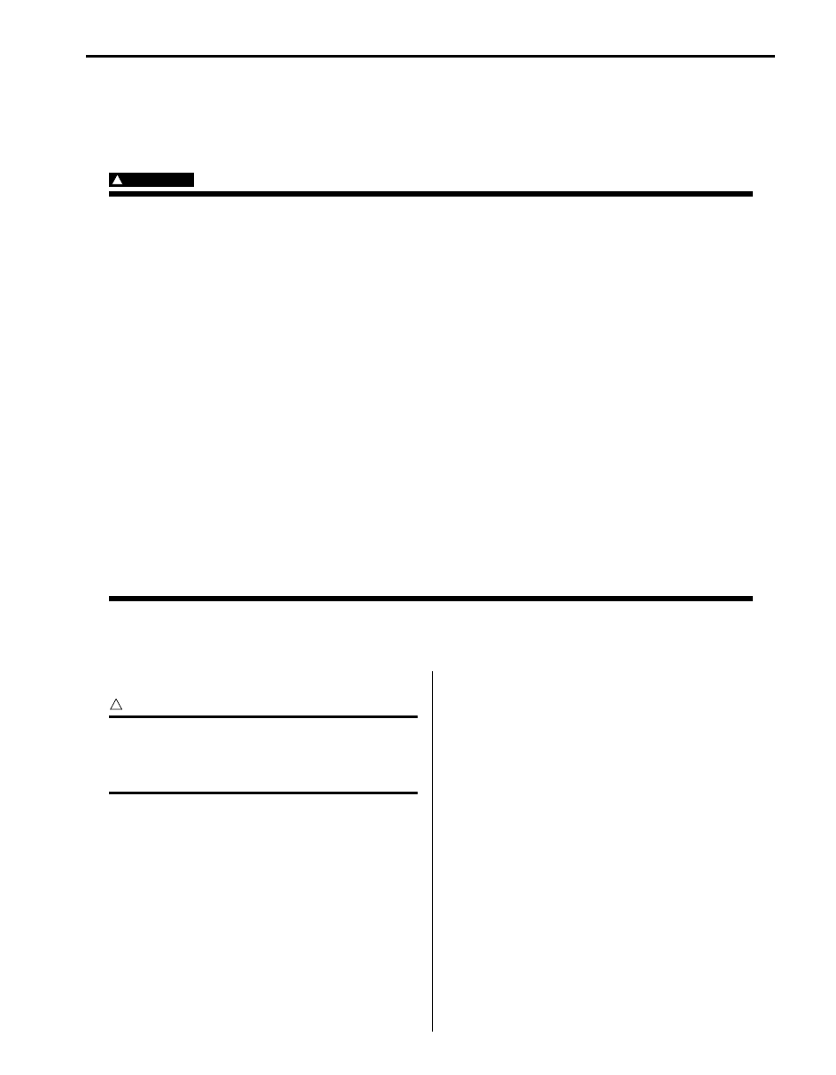
Water Pump Inspection
S5JB0A1606018
CAUTION
!
Do not disassemble water pump.
If any repair is required on pump, replace it
as assembly.
Rotate water pump by hand to check for smooth
operation. If pump does not rotate smoothly or makes
abnormal noise, replace it.
I5JB0A161016-01
I2RH0B160019-01
1F-14 Engine Cooling System:
Specifications
Tightening Torque Specifications
S5JB0A1607001
NOTE
The specified tightening torque is also described in the following.
“Cooling System Components”
Reference:
For the tightening torque of fastener not specified in this section, refer to “Fastener Information in Section 0A”.
Special Tools and Equipment
Recommended Service Material
S5JB0A1608001
Fastening part
Tightening torque
Note
N
⋅m
kgf-m
lb-ft
Water pump bolt and nut
25
2.5
18.0
Water pump bolt
25
2.5
18.0
Material
SUZUKI recommended product or Specification
Note
Water tight sealant
SUZUKI Bond No.1207F
P/No.: 99000–31250
Fuel System: 1G-1
Engine
Fuel System
Precautions
Precautions on Fuel System Service
S5JB0A1700001
WARNING
!
Before attempting service of any type on fuel system, the following should be always observed in
order to reduce the risk or fire and personal injury.
• Disconnect negative cable at battery.
• Do not smoke, and place no smoking signs near work area.
• Be sure to have CO
2
fire extinguisher handy.
• Be sure to perform work in a well-ventilated area and away from any open flames (such as gas hot
heater).
• Wear safety glasses.
• To relieve fuel vapor pressure in fuel tank, remove fuel filler cap from fuel filler neck and then
reinstall it.
• As fuel feed line is still under high fuel pressure even after stopping engine, loosening or
disconnecting fuel feed line directly may cause dangerous spout of fuel. Before loosening or
disconnecting fuel feed line, make sure to relieve fuel pressure referring to “Fuel Pressure Relief
Procedure”.
• A small amount of fuel may be released when the fuel line is disconnected. In order to reduce the
risk of personal injury, cover a shop cloth to the fitting to be disconnected. Be sure to put that cloth
in an approved container after disconnecting.
• Never run engine with fuel pump relay disconnected when engine and exhaust system are hot.
• Note that fuel hose connection varies with each type of pipe. Be sure to connect and clamp each
hose correctly referring to “Fuel Hose Disconnecting and Reconnecting”.
After connecting, make sure that it has no twist or kink.
• When installing injector or fuel feed pipe, lubricate its O-ring with gasoline.
General Description
Fuel System Description
S5JB0A1701001
CAUTION
!
This engine requires the unleaded fuel only.
The leaded and/or low lead fuel can result in
engine damage and reduce the effectiveness
of the emission control system.
The main components of the fuel system are fuel tank,
fuel pump assembly (with fuel filter and fuel level gauge),
fuel pressure regulator, fuel feed line and fuel vapor line.
For the details of fuel flow, refer to “Fuel Delivery System
Diagram”.
Fuel Delivery System Description
S5JB0A1701002
The fuel delivery system consists of the fuel tank, fuel
pump assembly (with built-in fuel filter), fuel pressure
regulator, delivery pipe, injectors, fuel return line, fuel
vapor line and fuel feed line.
The fuel in the fuel tank is pumped up by the fuel pump,
sent into delivery pipe and injected by the injectors.
As the fuel pump assembly is equipped with built-in fuel
filter, the fuel is filtered and its pressure is regulated after
being sent to the feed pipe.
The excess fuel at fuel pressure regulation process is
returned back into the fuel tank.
Also, fuel vapor generated in fuel tank is led through the
fuel vapor line into the EVAP canister.
For system diagram, refer to “Fuel Delivery System
Diagram”.
Нет комментариевНе стесняйтесь поделиться с нами вашим ценным мнением.
Текст