Suzuki Grand Vitara JB416 / JB420. Manual — part 302
8B-4 Air Bag System:
• Never attempt to disassemble the seat belt
pretensioners (retractor assembly).
• If any abnormality is found, be sure to replace it with
new one as an assembly.
• When an abnormality is noted as existing in the live
(inactivated) seat belt pretensioner, be sure to activate
it before discarding it.
• When grease, cleaning agent oil, water, etc., got on
the seat belt pretensioners (retractor assembly), wipe
it off immediately with a dry cloth.
• If seat belt pretensioner was dropped from a height of
30 cm (1 ft) or more, it should be replaced with a new
one as an assembly.
WARNING
!
• For handling and storage of a live seat belt
pretensioner, select a place where the
ambient temperature below 65
°C (150 °F),
without high humidity and away from
electric noise.
• Never carry the seat belt pretensioner by
webbing.
• When placing a live seat belt pretensioner
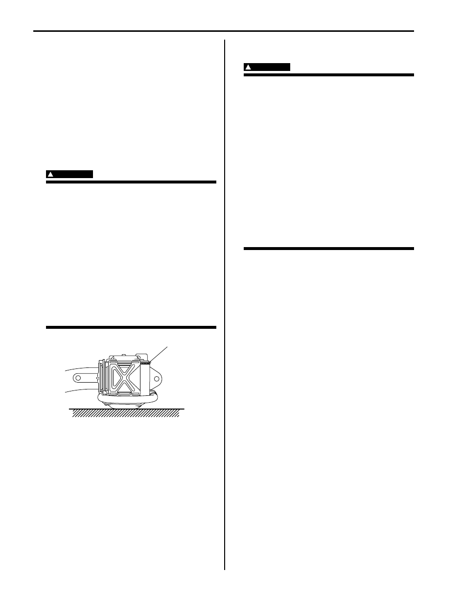
on the workbench or other surface, be sure
not to lay it with its exhaust hole (1)
provided side facing down. It is also
prohibited to put something on its face
with an exhaust hole (1) or to put a seat
belt pretensioner on top of another.
Otherwise, personal injury may result.
Deployed Air Bag (Inflator) Module and Activated
Seat Belt Pretensioner
WARNING
!
• The air bag (inflator) module and seat belt
pretensioner immediately after
deployment/activation is very hot. Wait for
at least 30 minutes to cool it off before
proceeding the work.
• Do not apply water, oil, etc. to deployed air
bag (inflator) module and to activate seat
belt pretensioner.
• After an air bag (inflator) module has been
deployed, the surface of the air bag may
contain a powdery residue. This powder
consists primarily of cornstarch (used to
lubricate the bag as it inflates) and by-
products of the chemical reaction. As with
many service procedures, gloves and
safety glasses should be worn.
• Wash your hands with mild soap and water
after completing the work.
Refer to the procedure described under “Deployed Air
Bag (Inflator) Module and Activated Seat Belt
Pretensioner Disposal” for disposal.
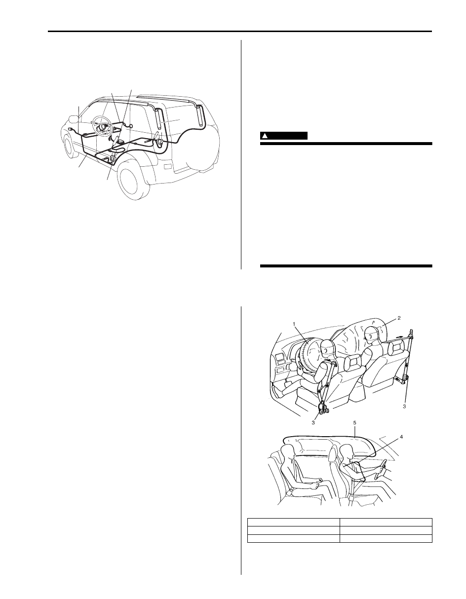
Air Bag Wire Harness and Connector
Air bag wire harness is included in main harness (1),
instrument panel harness (2), floor harness (3) and seat
harness (4). Air bag wire harness can be identified easily
as the part of connector side wire harness is covered
with a yellow protection tube. Be very careful when
handling it.
• When an open in air bag wire harness, damaged wire
harness, connector or terminal is found, replace wire
harness, connectors and terminals as an assembly.
• When installing it, be careful so that the air bag wire
harness is not caught or does not interfere with other
parts.
1
I2RH01820048-01
Air Bag System: 8B-5
• Make sure air bag system grounding point (5) is clean
and ground is securely fastened for optimum metal-to-
metal contact. Poor grounding can cause intermittent
problems that are difficult to diagnose.
Precautions on Disposal of Air Bag and Seat
Belt Pretensioner
S5JB0A8200003
Do not dispose of the live (undeployed) air bag (inflator)
modules and the live (inactivated) seat belt
pretensioners.
When disposal is necessary, be sure to deploy / activate
the air bag and seat belt pretensioner according to
deployment / activation procedure described in “Air Bag
(Inflator) Module and Seat Belt Pretensioner Disposal”.
WARNING
!
Failure to follow proper air bag (inflator)
module and seat belt pretensioner disposal
procedures can result in air bag deployment
and pretensioner activation which could
cause personal injury. Undeployed air bag
(inflator) module and inactivated seat belt
pretensioner must not be disposed of
through normal refuse channels.
The undeployed air bag (inflator) module and
inactivated seat belt pretensioner contain
substances that can cause severe illness or
personal injury if the sealed container is
damaged during disposal.
General Description
Air Bag System Construction
S5JB0A8201001
With the air bag system which includes front air bags,
side curtain-air bag and side-air bags for both the
driver’s and passenger’s sides as well as the seat belt
pretensioners, the sag of the seat belt is taken up (for
seat belt with pretensioner), the driver air bag (inflator)
module is deployed from the center of the steering
column and the passenger air bag (inflator) module from
the top of the instrument panel in front of the front
passenger seat in occurrence of a front collision with an
impact larger than a certain set value to supplement
protection offered by the driver and front passenger seat
belts.
Side-air bag (inflator) module is deployed from the side
of the seat back in occurrence of a sideward collision
with an impact larger than a certain set value.
Side curtain-air bag (inflator) module is deployed from
the roof side in occurrence of a sideward collision with
an impact larger than a certain set value.
5
2
1
3
4
I5JB0A820006-01
1. Driver air bag
4. Side-air bag
2. Passenger air bag
5. Side curtain-air bag
3. Seat belt pretensioner
I4RS0B820002-02
8B-6 Air Bag System:
The air bag system is designed to activate only in severe
frontal and sideward collisions. It is not designed to
activate in rear impacts, rollovers, or minor frontal and
sideward collisions, since it would offer no protection in
those types of accidents.
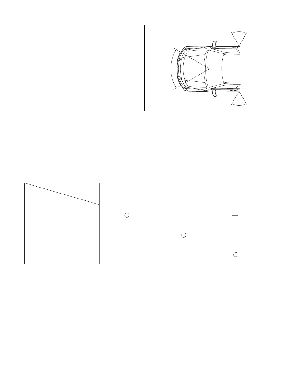
Air Bag System Input / Output Table
S5JB0A8201002
There are two types of air bag system of this model
• Consisting of 4 items, i.e., air bags for driver and front passenger and seat belts with pretensioner for driver and
front passenger sides
• Consisting of 8 items, i.e., air bags for driver and front passenger, seat belts with pretensioner for driver and front
passenger sides, side-air bags for driver and front passenger and curtain-air bags for driver and front passenger
sides
The side-air bag and curtain-air bag on the same side deploy at the same time only when an impact is applied to
that side. For the details, refer to the table below.
I5JB0A820007-01
INPUT
Sensor in SDM and
forward-sensor
Driver side-air bag
and Driver side
curtain-air bag
Passenger side-air bag
and Passenger side
curtain-air bag
Driver side-sensor
Passenger side-sensor
OUTPUT
Signal from
sensor
Driver air bag, Passenger
air bag, Seat belt with
pretensioner (LH) and Seat
belt with pretensioner (RH)
I4RS0A820005-01
Air Bag System: 8B-7
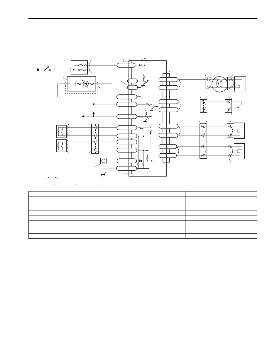
Schematic and Routing Diagram
Air Bag System Wiring Circuit Diagram
S5JB0A8202001
Air bag system without side-air bag and curtain-air bag
GRN/ORN
GRN/YEL
BLU/ORN
BLU/YEL
GRN/ORN
GRN/YEL
BLU/ORN
BLU/YEL
12V
5V
5V
YEL
ORN
PNK/BLK
ORN
PNK/BLK
PPL/WHT
“E77”
“G06”
“L36”
“E24”
“E13”
PPL
BLK
“G34”
G47-18
G47-16
G47-22
G47-13
G47-4
G47-8
G47-7
G47-1
G47-2
G47-14
G47-20
L2
L1
ADS
IG
ST
G47-9 FD+
G47-17 FD-
DNS
GND
WL
PP-
PP+
DP-
DP+
“L12”
“G55” “L29”
“G47”
“G47”
12V
1
2
6
8
4
5
RED
PPL/RED
BLK/YEL
YEL/BLK
“G01”
7
“G28”
“G03”
PNK
PNK/BLU
PNK
PNK/BLU
G47-11 FP+
G47-19 FP-
[C]
[D]
“E13” “E77”, “G01” “G68”, “L12” “L36” and “Q01”
G47-3
G47-5
G47-6
GRN/RED
GRN
BLU/RED
YEL/RED
BLU/RED
YEL/RED
“G65”
[B] “G27”
[A] “G26”
“G68”
“G67”
“Q01”
D1+
D1-
P1+
P1-
3
10
12
11
13
14
16
9
22
15
17
18
19
20
21
I5JB0A820008-01
[A]: For vehicle without cruise control system
6. Combination meter
15. Ground for air bag system
[B]: For vehicle with cruise control system
7. Lamp driver
16. SDM
[C]: Shorting bar
8. “AIR BAG” warning lamp
17. Contact coil
[D]: Connector
9. Connection detection pin
18. Driver air bag (inflator) module
1. To battery
10. To BCM
19. Passenger air bag (inflator) module
2. Ignition switch
11. To data link connector (DLC)
20. Driver seat belt pretensioner
3. Junction block assembly
12. To ECM, TCM, BCM, ABS hydraulic unit / control
module assembly and 4WD control module
21. Passenger seat belt pretensioner
4. “A/B” fuse
13. Driver forward-sensor
22. “AIR BAG” monitor coupler (if equipped)
5. “METER” fuse
14. Passenger forward-sensor
Нет комментариевНе стесняйтесь поделиться с нами вашим ценным мнением.
Текст