Suzuki Grand Vitara JB416 / JB420. Manual — part 292
7B-59 Air Conditioning System:
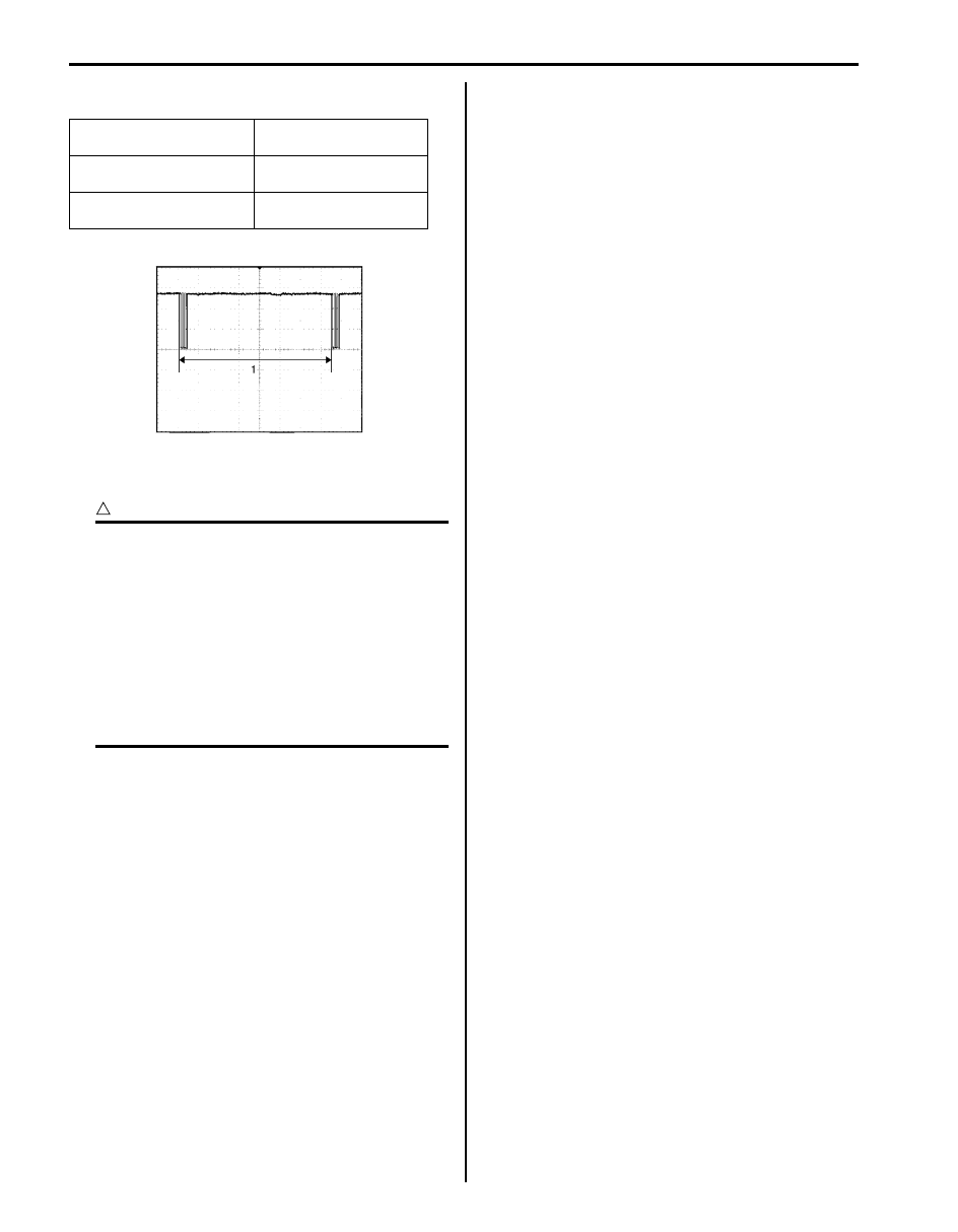
Reference waveform No. 1
Serial communication line to BCM (1)
A/C System Inspection at ECM
S5JB0A7204051
CAUTION
!
• ECM connectors are waterproofed. Each
terminal of the ECM connectors is sealed
up with the grommet. Therefore, do not
measure circuit voltage and resistance by
inserting the tester’s probe into the sealed
terminal at the harness side. Or, ECM and
its circuits may be damaged by water.
• ECM (PCM) cannot be checked by itself.
It is strictly prohibited to connect voltmeter
or ohmmeter to ECM (PCM) with couplers
disconnected from it.
Voltage Check
ECM (PCM) and its circuits can be checked at ECM
(PCM) wiring couplers by measuring voltage as follows.
Refer to “Inspection of ECM and Its Circuits in Section
1A”.
• C37-12 A/C refrigerant pressure sensor signal
• C37-14 Output of 5 V power source
• C37-15 Ground for ECM
• C37-24 Engine coolant temp. (ECT) sensor signal
• C37-29 Ground for ECM
• C37-30 Ground for ECM
• C37-48 Ground for ECM
• C37-52 CMP sensor signal
• C37-57 Ground for sensors
• C37-58 Ground for ECM
• E23-4 CAN (high) communication line (active high
signal) to ABS control module
• E23-16 Main power supply
• E23-19 CAN (low) communication line (active low
signal) to ABS control module
• E23-46 Radiator fan relay No.1 output
• E23-47 Radiator fan relay No.2 output
• E23-48 Radiator fan relay No.3 output
• E23-49 A/C compressor relay output
Measurement terminal
CH1: “G52-11” to “G52-
17”
Oscilloscope setting
CH1: 5 V / DIV
TIME: 20 ms / DIV
Measurement condition
Ignition switch is at ON
position
I5JB0A720091-01
Air Conditioning System: 7B-60
Repair Instructions
Operation Procedure for Charging A/C with Refrigerant
S5JB0A7206001
WARNING
!
• Your eyes should not be exposed to refrigerant (liquid).
Any liquid Refrigerant-134a escaping by accident shows a temperature as low as approx. –6
°C (21.2
°F) below freezing point. Should liquid HFC-134a (R-134a) get into your eyes, it may cause a serious
injury. To protect your eyes against such accident, it is necessary to always wear goggles. Should it
occur that HFC-134a (R-134a) strikes your eye(s), consult a doctor immediately.
– Do not use your hand to rub the affected eye(s). Instead, use quantities of fresh cold water to
splash it over the affected area to gradually raise temperature of such area above freezing point.
– Obtain proper treatment as soon as possible from a doctor or eye specialist.
• Should the liquid refrigerant HFC-134a (R-134a) is exposed to your skin, the affected area should be
treated in the same manner as when skin is frostbitten or frozen.
• Do not handle refrigerant near any place where welding or steam cleaning is performed.
• Refrigerant should be kept in a cold and dark place. It should never be stored in any place where
temperature is high, e.g. where exposed to direct sun light, close to fire or inside vehicle (including
trunk room).
• Avoid breathing fume produced when HFC-134a (R-134a) is burned. Such fume may be hazardous to
your health.
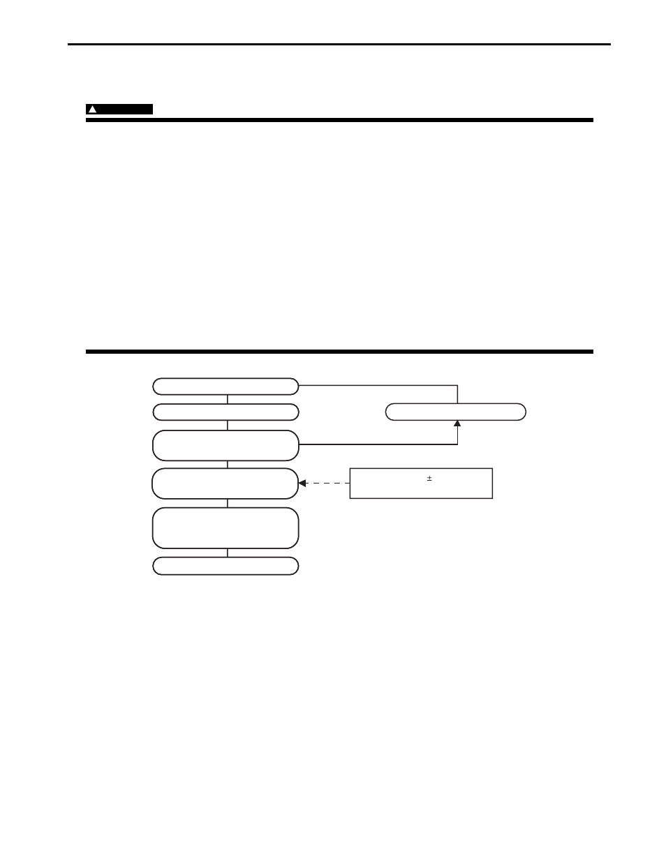
Star
Start e
t evacuation.
acuation.
Stop e
Stop evacuation.
acuation.
20 min
20 minutes (abo
utes (above 760 mmHg)
e 760 mmHg)
Wait 10 min
ait 10 minutes
utes
Chec
Check A/C system f
k A/C system for
or
pressure tighteness
pressure tighteness.
Recharge A/C system with
Recharge A/C system with
refr
refriger
igerant.
ant.
Chec
Check A/C system f
k A/C system for refr
or refriger
igerant
ant
leaks and amount of refr
leaks and amount of refriger
igerant
ant
charged.
charged.
Perf
erfor
ormance test
mance test
Inspect and repair connections
Inspect and repair connections.
If gauge sho
If gauge shows
ws
abnor
abnormal conditions
mal conditions
Recharge 570 30 g of
Recharge 570 30 g of
refr
refriger
igerant.
ant.
I5JB0A720031-02
7B-61 Air Conditioning System:
Recovery
When discharging refrigerant out of A/C system, always
recover it by using refrigerant recovery and recycling
equipment (1). Discharging refrigerant HFC-134a
(R134a) into atmosphere would cause adverse effect to
environments.
NOTE
• After recovering refrigerant from system
the amount of removed compressor oil
must be measured for replenishing
compressor oil. Refer to “Precautions on
Replenishing Compressor Oil”.
• When handling recovery and recycling
equipment, be sure to follow the
instruction manual for the equipment.
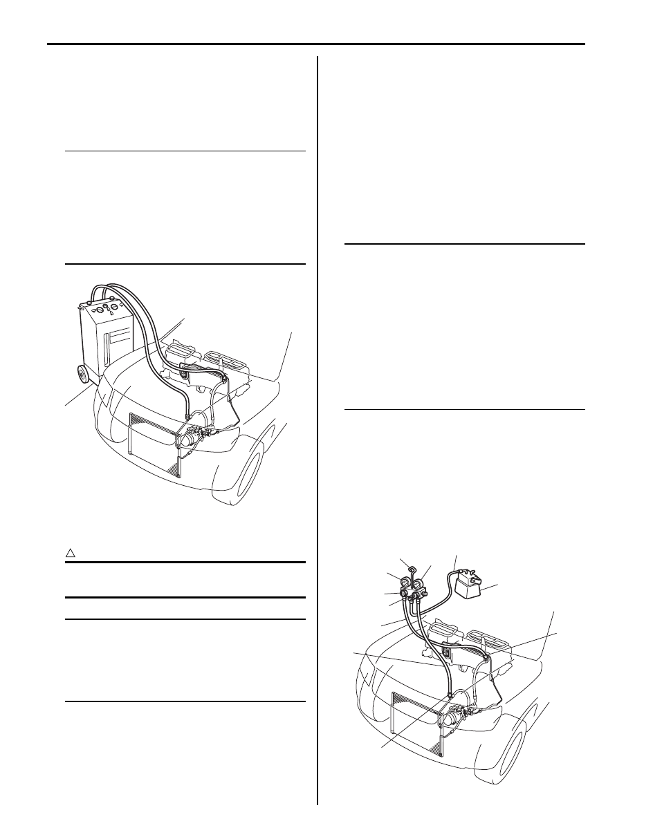
Evacuation
CAUTION
!
Do not evacuate before recovering
refrigerant in system.
NOTE
Once A/C system circuit is opened (exposed
to atmospheric air) air conditioning system
must be evacuated by using a vacuum pump.
The A/C system should be attached with a
manifold gauge set, and should be evacuated
for approx. 20 minutes.
1) Connect high charging hose (1) and low charging
hose (2) of manifold gauge set (3) respectively as
follows:
High charging hose (1)
→ High pressure charging
valve (4) on discharge hose
Low charging hose (2)
→ Low pressure charging
valve (5) on suction pipe
2) Attach center charging hose (6) of manifold gauge
set (3) to vacuum pump (7).
3) Operate vacuum pump (7), and then open
discharge-side valve (9) (Hi) of manifold gauge set
(3).
If there is no blockage in the system, there will be an
indication on high pressure gauge (10).
In this case, open the other-side valve (8) (Lo) of the
set and repair the system.
4) Approx. 10 minutes later, low pressure gauge (11)
should show a vacuum lower than –100 kPa (–1.0
kg/cm
2
, –760 mmHg, –14.2 psi) providing no
leakage exists.
NOTE
• If the system does not show a vacuum
below –100 kPa (–1.0 kg/cm
2
, –760 mmHg,
–14.2 psi), close both valves, stop vacuum
pump and watch movement of low
pressure gauge.
• Increase in the gauge reading suggests
existence of leakage. In this case, repair
the system before continuing its
evacuation.
• If the gauge shows a stable reading
(suggesting no leakage), continue
evacuation.
5) Evacuation should be carried out for a total of at
least 20 minutes.
6) Continue evacuation until low pressure gauge
indicates a vacuum less than –100 kPa (–1.0 kg/cm
2
,
–760 mmHg, –14.2 psi), and then close both valves
(8), (9).
7) Stop vacuum pump (7). Disconnect center charging
hose (6) from pump inlet. Now, the system is ready
for charging refrigerant.
1
I5JB0A720032-01
8
9
2
1
4
5
11
3
10
6
7
I5JB0A720033-01

Air Conditioning System: 7B-62
Checking of A/C System for Pressure Leaks
After completing the evacuation, close manifold gauge
high pressure valve (Hi) and low-pressure valve (Lo) and
wait 10 minutes. Verify that low-pressure gauge reading
has not changed.
CAUTION
!
If the gauge reading moves closer to “0”,
there is a leak somewhere. Inspect the tubing
connections, make necessary corrections.
And then evacuate system once again and
make sure that there are no leaks.
Charge
CAUTION
!
• Because the sight glass is not used for this
A/C system, do not perform an additional
charge to the A/C system. To charge the
proper amount of refrigerant, recover and
evacuate the A/C system first. And then,
charge the proper amount of refrigerant
into the A/C system.
• Always charge through low pressure-side
of A/C system at after the initial charging is
performed from the high-pressure side
with the engine stopped.
• Never charge to high pressure-side of A/C
system with engine running.
• Do not charge while compressor is hot.
• When installing tap valve to refrigerant
container to make a hole there through,
carefully follow directions given by
manufacturer.
• A pressure gauge should always be used
before and during charging.
• The refrigerant container should be
emptied of refrigerant when discarding it.
• The refrigerant container should not be
heated up to 40
°C (104 °F) or over.
• Refrigerant container should not be
reversed in direction during charging.
Reversing in direction causes liquid
refrigerant to enter compressor, causing
troubles, such as compression of liquid
refrigerant and the like.
NOTE
The A/C system contains HFC-134a (R-134a).
Described here is a method to charge the A/C
system with refrigerant from the refrigerant
service container.
When charging refrigerant recovered by
using the refrigerant and recycling
equipment (when recycling refrigerant),
follow the procedure described in the
equipment manufacturer’s instruction
manual.
Charge proper amount of refrigerant accurately in
accordance with the following procedure.
Specified amount of refrigerant
570
± 30 g (20.1 ± 1.0 oz)
The initial charging of the A/C system is performed from
the high-pressure side with the engine stopped.
And next, this method must be followed by charging from
the low-pressure side with the engine running.
1) Check to make sure that hoses are routed properly
after evacuating the system.
2) Connect low charging hose (1) and high charging
hose (2) of the manifold gauge set (3) in position.
Thus open refrigerant container valve (4) to purge
the charging line.
3) Open the high-pressure side valve (6) and charge
refrigerant to system.
4) After a while, open the low-pressure side valve (5)
and close the high-pressure side valve (6).
WARNING
!
Make sure that high pressure-side valve is
closed securely.
5
6
1
2
3
4
I5JB0A720034-01
Нет комментариевНе стесняйтесь поделиться с нами вашим ценным мнением.
Текст