Suzuki Grand Vitara JB416 / JB420. Manual — part 207

4E-5 ABS:
4. Circuit fuse box
16. Right-front wheel speed sensor
28. Brake fluid level switch
5. Combination meter
17. Left-front wheel speed sensor
29. Parking brake switch
6. ABS warning lamp
18. Data link connector
30. CAN junction
7. EBD warning lamp (Brake warning lamp)
19. To ECM, TCM, SDM, BCM and 4WD
control module
31. To TCM, 4WD control module and keyless
start control module
8. Lamp driver module
20. Stop lamp
32. CAN communication line
9. ABS hydraulic unit / control module assembly
21. Brake light switch
10. Solenoid valve power supply driver (transistor)
22. Power control unit
Terminal
Wire color
Circuit
E03
1
WHT/BLU
ABS pump motor driver (Transistor)
2
—
—
3
—
—
4
—
—
5
PPL/WHT
Dark link connector
6
WHT
CAN communication line (low) for combination meter
7
GRN/ORN
Ignition switch
8
WHT/BLU
CAN communication line (low) for ECM
9
—
—
10
WHT/RED
CAN communication line (high) for ECM
11
—
—
12
RED
CAN communication line (high) for combination meter
13
BLK
Ground
14
WHT/RED
Solenoid valve power supply driver (Transistor)
15
YEL/BLK
Left–rear wheel speed sensor (–)
16
YEL
Left–rear wheel speed sensor (+)
17
—
—
18
GRN
Right–front wheel speed sensor (+)
19
GRN/BLK
Right–front wheel speed sensor (–)
20
—
—
21
BLU/BLK
Left–front wheel speed sensor (–)
22
BLU
Left–front wheel speed sensor (+)
23
—
—
24
LT GRN
Right–rear wheel speed sensor (+)
25
LT GRN/BLK
Right–rear wheel speed sensor (–)
26
BLK
Ground
ABS: 4E-6
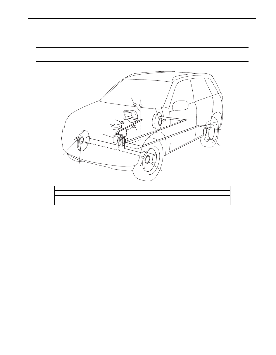
Component Location
ABS Components Location
S5JB0A4503001
NOTE
As for the difference of RH steering vehicle and LH steering vehicle, the location of the combination
meter, data link connector, stop lamp switch and the brake master cylinder assembly only changes.
6
2
1
7
4
5
6
2
3
2
6
6
2
8
I5JB0A450006-01
1. ABS hydraulic unit / control module assembly
5. EBD warning lamp (Brake warning lamp)
2. Wheel speed sensors
6. Wheel encoder (included in wheel hub assembly)
3. Stop lamp switch
7. Data link connector
4. ABS warning lamp
8. ECM

4E-7 ABS:
Diagnostic Information and Procedures
ABS Check
S5JB0A4504001
Refer to the following items for the details of each step.
Step
Action
Yes
No
1
Malfunction analysis
1) Perform “Customer complaint analysis: ”.
2) Perform “Problem symptom confirmation: ”.
3) Perform “DTC check, record and clearance: ” and
recheck DTC.
Is there any malfunction DTC?
Go to Step 4.
Go to Step 2.
2
Driving test
1) Perform “Step 2: Driving Test: ”.
Is trouble symptom identified?
Go to Step 3.
Go to Step 6.
3
DTC check
1) Perform “DTC Check”.
Is it malfunction code?
Go to Step 4.
Go to Step 5.
4
ABS check
1) Inspect and repair referring to applicable DTC flow.
Does trouble recur?
Go to Step 5.
Go to Step 7.
5
Brakes diagnosis
1) Inspect and repair referring to “Brakes Symptom
Does trouble recur?
Go to Step 3.
Go to Step 7.
6
Check for intermittent problem
1) Check intermittent troubles referring to “Intermittent and
Poor Connection Inspection in Section 00” and related
circuit of trouble code recorded in Step 1.
Does trouble recur?
Go to Step 4.
Go to Step 7.
7
Final confirmation test
1) Perform “Step 7: Final Confirmation Test: ”.
Does trouble recur?
Go to Step 3.
End.
ABS: 4E-8
Step 1: Malfunction Analysis
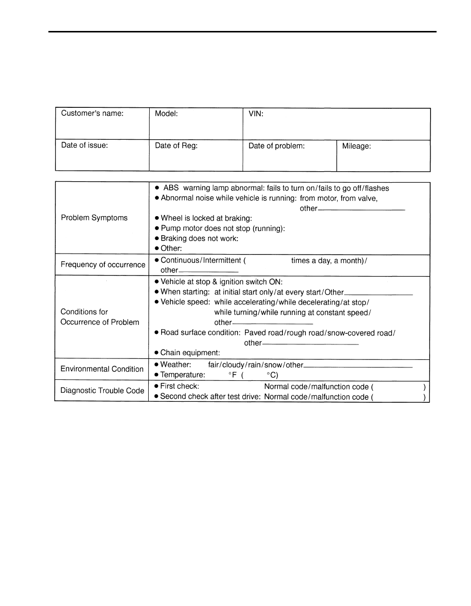
Customer complaint analysis
Record details of the problem (failure, complaint) and how it occurred as described by the customer.
For this purpose, use of such a questionnaire form as shown in the following will facilitate collecting information to the
point required for proper analysis and diagnosis.
Customer questionnaire (Example)
Problem symptom confirmation
Check if what the customer claimed in “Customer Questionnaire” is actually found in the vehicle and if that symptom is
found, whether it is identified as a failure. (This step should be shared with the customer if possible.) Check warning
lamps related to brake system referring to “EBD Warning Lamp (Brake Warning Lamp) Check” and “ABS Warning
Lamp Check”.
DTC check, record and clearance
Perform “DTC Check” procedure, record it and then clear it referring to “DTC Clearance”.
Recheck DTC referring to “DTC Check”.
When DTC which is recorded at DTC check procedure is detected again after performing DTC clearance, go to “Step
4: ABS Check: ” to proceed the diagnosis.
When DTC which is recorded at DTC check procedure is not indicated anymore after performing DTC clearance, ABS
control module does not perform the system diagnosis, or temporary abnormality may occur, therefore go to “Step 2:
Driving Test: ” to proceed the diagnosis.
I2RH01450014-01
Нет комментариевНе стесняйтесь поделиться с нами вашим ценным мнением.
Текст