Suzuki Grand Vitara JB416 / JB420. Manual — part 215
4E-37 ABS:
Front Wheel Speed Sensor Inspection
S5JB0A4506007
Check sensor for damage.
If any malcondition is found, replace.
Rear Wheel Speed Sensor On-Vehicle
Inspection
S5JB0A4506008
Refer to “Front Wheel Speed Sensor On-Vehicle
Inspection” since rear wheel speed sensor is the same
as front wheel speed sensor.
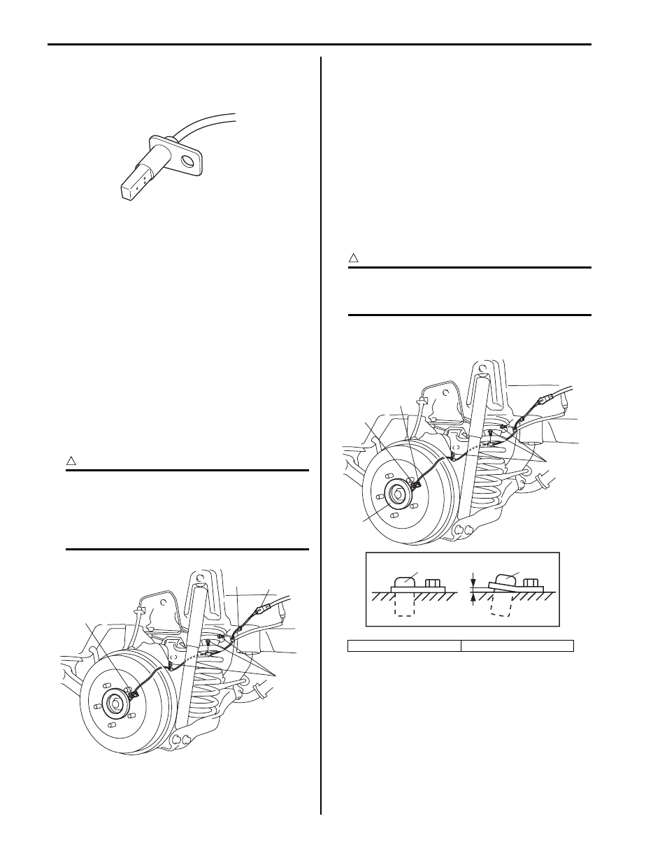
Rear Wheel Speed Sensor Removal and
Installation
S5JB0A4506009
Removal
1) Disconnect negative cable from battery.
2) Disconnect rear wheel speed sensor coupler (1).
3) Hoist vehicle and remove wheel.
4) Remove harness clamp (4) and clamp bolts (2).
5) Remove rear wheel speed sensor (3) from knuckle.
CAUTION
!
• Do not pull wire harness when removing
rear wheel speed sensor.
• Do not cause damage to surface of rear
wheel speed sensor and do not allow dust,
etc. to enter its installation hole.
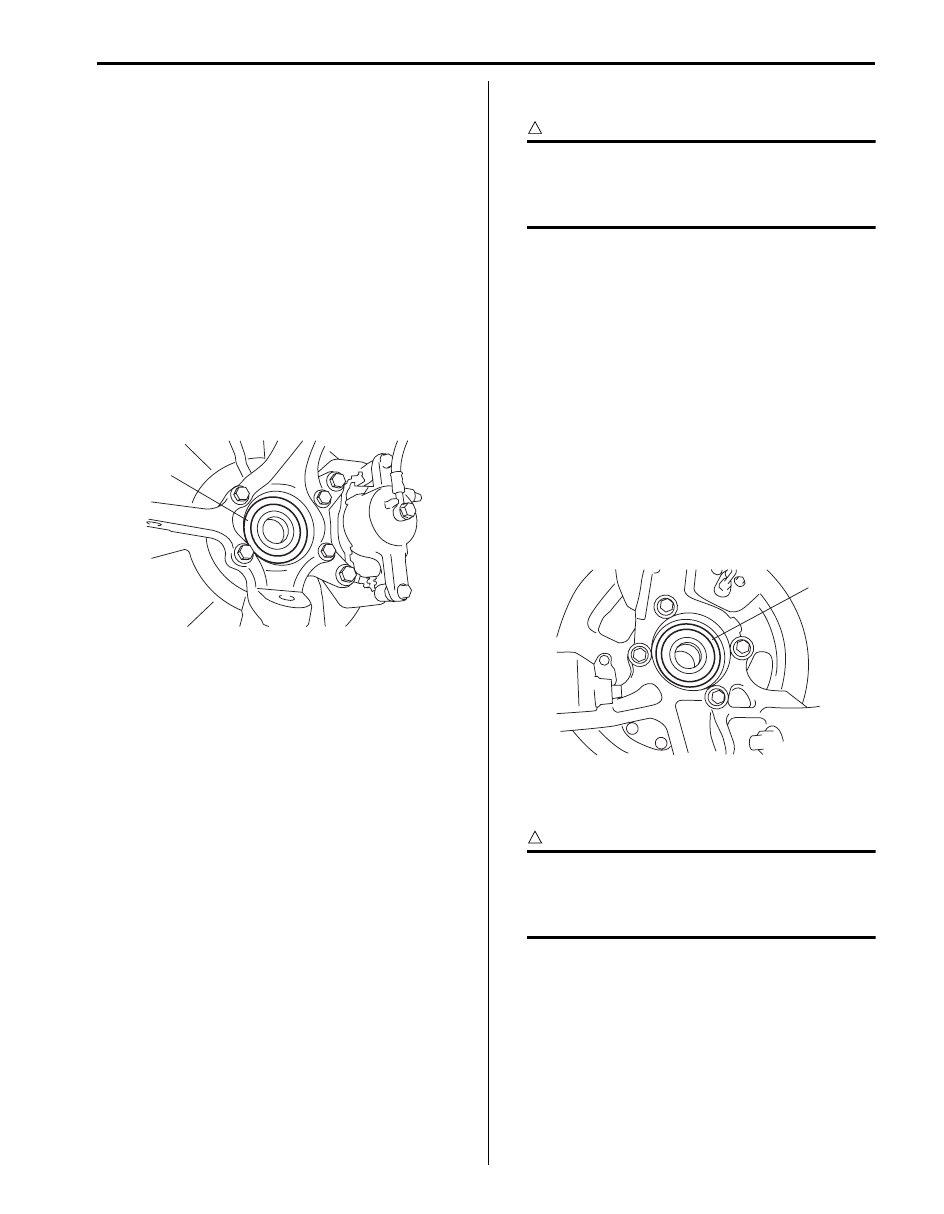
Installation
Reverse removal procedure for installation noting the
following.
• Check that no foreign material is attached to sensor
(1) and mating encoder (2).
• Be sure to install wheel speed sensor (1) and its bolt
at the correct (upper) position as shown in figure.
Tighten sensor bolt and harness clamp bolts to
specified torque.
Tightening torque
Rear wheel speed sensor bolt (a): 11 N·m (1.1 kgf-
m, 8.0 lb-ft)
Rear wheel speed sensor harness clamp bolt
(b): 11 N·m (1.1 kgf-m, 8.0 lb-ft)
CAUTION
!
Do not pull or twist wire harness more than
necessary when installing rear wheel speed
sensor.
• Check that there is no clearance between sensor and
brake back plate.
I5JB0A450031-01
3
1
2
4
I5JB0A450032-02
[A]: OK
[B]: NG
[A]
[B]
2
1
(a)
(b)
1
1
I5JB0A450033-01
ABS: 4E-38
Rear Wheel Speed Sensor Inspection
S5JB0A4506010
Refer to “Front Wheel Speed Sensor Inspection” since
rear wheel speed sensor is the same as front wheel
speed sensor.
Front Wheel Encoder On-Vehicle Inspection
S5JB0A4506011
Before inspect front wheel encoder, remove front drive
shaft referring to “Front Drive Shaft Assembly Removal
and Installation: Front in Section 3A”.
• Check encoder (1) for being crack, damaged or
deformed.
• Turn wheel and check if encoder rotation is free from
eccentricity and looseness.
• Check that no foreign material is attached.
If any faulty is found, repair or replace. Refer to “Front
Wheel Hub Assembly Removal and Installation in
Section 2B”.
Front Wheel Encoder Removal and Installation
S5JB0A4506012
CAUTION
!
Front wheel encoder is included in front
wheel hub assembly. If front wheel encoder
needs to replaced, replace it as a front wheel
hub assembly.
For removal and installation of front wheel hub
assembly, referring to “Front Wheel Hub Assembly
Removal and Installation in Section 2B”.
Rear Wheel Encoder On-Vehicle Inspection
S5JB0A4506013
Before inspect rear wheel encoder, remove rear drive
shaft referring to “Rear Drive Shaft Assembly Removal
and Installation: Rear in Section 3A”.
• Check encoder (1) for being crack, damaged or
deformed.
• Turn wheel and check if encoder rotation is free from
eccentricity and looseness.
• Check that no foreign material is attached.
If any faulty is found, repair or replace. Refer to “Rear
Wheel Hub Assembly Removal and Installation in
Section 2C”.
Rear Wheel Encoder Removal and Installation
S5JB0A4506014
CAUTION
!
Rear wheel encoder is included in rear wheel
hub assembly. If rear wheel encoder needs to
replaced, replace it as a rear wheel hub
assembly.
For removal and installation of front wheel hub
assembly, referring to “Rear Wheel Hub Assembly
Removal and Installation in Section 2C”.
1
I5JB0A450034-01
1
I5JB0A450035-01
4E-39 ABS:
Specifications
Tightening Torque Specifications
S5JB0A4507001
NOTE
The specified tightening torque is also described in the following.
“ABS Hydraulic Unit / Control Module Assembly Components”
Reference:
For the tightening torque of fastener not specified in this section, refer to “Fastener Information in Section 0A”.
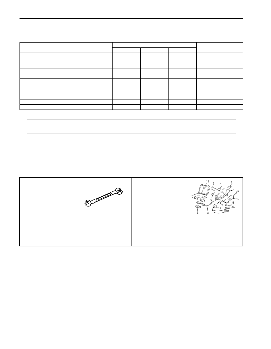
Special Tools and Equipment
Special Tool
S5JB0A4508001
Fastening part
Tightening torque
Note
N
⋅m
kgf-m
lb-ft
Brake pipe flare nut
16
1.6
11.5
ABS hydraulic unit / control module assembly
bolt
9
0.9
6.5
ABS hydraulic unit / control module assembly
bracket bolt
25
2.5 18.0
ABS hydraulic unit / control module assembly
bracket nut
25
2.5 18.0
Front wheel speed sensor bolt
11
1.1
8.0
Front wheel speed sensor harness clamp bolt
11
1.1
8.0
Rear wheel speed sensor bolt
11
1.1
8.0
Rear wheel speed sensor harness clamp bolt
11
1.1
8.0
09950–78220
SUZUKI scan tool
Flare nut wrench (10 mm)
—
This kit includes following
items. 1. Tech 2, 2. PCMCIA
card, 3. DLC cable, 4. SAE
16/19 adapter, 5. Cigarette
cable, 6. DLC loop back
adapter, 7. Battery power
cable, 8. RS232 cable, 9.
RS232 adapter, 10. RS232
loop back connector, 11.
Storage case, 12. Power
supply ) / )
Table of Contents 5- i
5
Section 5
CONTENTS
Transmission / Transaxle
Precautions . . . . . . . . . . . . .5-1
Precautions. . . . . . . . . . . . . . . . 5-1
Precautions for Transmission / Transaxle. . . . 5-1
Automatic Transmission/Transaxle. ... 5A-1
Precautions. . . . . . . . . . . . . . ...5A-1
Reassembly . . . . . . . . . . . . . .. 5A-1
General Description . . . . . . . . . . . .5A-3
Automatic Transmission Description. . . . ... 5A-3
Clutch / Brake Functions of Automatic
Transmission. . . . . . . . . . . . . . 5A-5
Table of A/T System Component Operation . ... 5A-6
Automatic Gear Shift Table. . . . . . . . . 5A-7
CAN Communication System Description. . ... 5A-9
Electronic Shift Control Input / Output Table. .5A-11
Brake Interlock System Description . . . . ..5A-12
A/T Diagnosis General Description . . . . ...5A-12
On-Board Diagnostic System Description. . .5A-12
Schematic and Routing Diagram. . . . . ..5A-14
Electronic Shift Control Input / Output
Diagram . . . . . . . . . . . . . . ..5A-14
Electronic Shift Control System Wiring
Diagram . . . . . . . . . . . . . . ..5A-15
Component Location . . . . . . . . . . .5A-17
Electronic Shift Control System Components
Location . . . . . . . . . . . . . . ..5A-17
Diagnostic Information and Procedures. . ..5A-18
A/T System Check . . . . . . . . . . . 5A-18
Malfunction Indicator Lamp (MIL) Check . . .. 5A-20
Transmission Warning Light Operation Check
(Vehicle is Equipped with Engine Diagnosis
Connector) . . . . . . . . . . . . . ..5A-20
“POWER” Lamp Operation Check . . . . . 5A-20
DTC Table. . . . . . . . . . . . . . .5A-21
DTC Check . . . . . . . . . . . . . ...5A-22
DTC Clearance . . . . . . . . . . . . . 5A-23
Fail Safe Table. . . . . . . . . . . . .. 5A-24
Scan Tool Data . . . . . . . . . . . . . 5A-26
Visual Inspection. . . . . . . . . . . ...5A-29
A/T Basic Check . . . . . . . . . . . ...5A-29
Road Test . . . . . . . . . . . . . . .5A-30
Manual Road Test. . . . . . . . . . . .5A-31
Stall Test . . . . . . . . . . . . . . ...5A-32
Time Lag Test . . . . . . . . . . . . ...5A-33
Line Pressure Test . . . . . . . . . . . 5A-34
Engine Brake Test. . . . . . . . . . . .5A-35
“P” Range Test. . . . . . . . . . . . ..5A-35
A/T Symptom Diagnosis. . . . . . . . . 5A-36
No Gear Shift to 4th Gear . . . . . . . . .5A-43
No Lock-Up Occurs. . . . . . . . . . ...5A-44
Transmission Warning Light Circuit Check –
Transmission Warning Light Circuit Check –
“POWER” Light Circuit Check – Light Does
Not Come “ON” at Ignition Switch ON. . . .5A-46
DTC P0705: Transmission Range Sensor
Circuit Malfunction. . . . . . . . . . ...5A-46
DTC P0707: Transmission Range Sensor
Circuit Low . . . . . . . . . . . . . ..5A-48
DTC P0712: Transmission Fluid Temperature
Sensor “A” Circuit Low . . . . . . . . . 5A-50
DTC P0713: Transmission Fluid Temperature
Sensor “A” Circuit High . . . . . . . . ...5A-51
DTC P0717: Input / Turbine Speed Sensor
Circuit No Signal . . . . . . . . . . . .5A-52
DTC P0722: Output Speed Sensor Circuit No
Signal . . . . . . . . . . . . . . . ..5A-53
DTC P0741 / P0742: TCC Circuit
Performance or Stuck OFF / TCC Circuit
Stuck ON. . . . . . . . . . . . . . .5A-54
DTC P0751 / P0752: Shift Solenoid-A
Performance or Stuck OFF / Shift Solenoid-
A Stuck ON . . . . . . . . . . . . . .5A-55
DTC P0756 / P0757: Shift Solenoid-B
Performance or Stuck OFF / Shift Solenoid-
B Stuck ON . . . . . . . . . . . . . .5A-56
DTC P0962: Pressure Control Solenoid “A”
Control Circuit Low. . . . . . . . . . ..5A-57
Нет комментариевНе стесняйтесь поделиться с нами вашим ценным мнением.
Текст