Suzuki Grand Vitara JB416 / JB420. Manual — part 16
1A-13 Engine General Information and Diagnosis:
Electronic Control System Description
S5JB0A1101007
The electronic control system consists of 1) various sensors which detect the state of engine and driving conditions, 2)
ECM which controls various devices according to the signals from the sensors and 3) various controlled devices.
Functionally, it is divided into the following sub systems:
• Fuel injection control system
• Ignition control system
• Intake manifold tuning valve control system (for J20 engine)
• Electric Throttle Body Control System
• Fuel pump control system
• Radiator cooling fan control system
• Evaporative emission control system (if equipped)
• EGR system
• A/F sensor heater control system (if equipped)
• Oxygen sensor heater control system (if equipped)
• A/C control system (if equipped with A/C)
• Camshaft position control system (for M16 engine)
• Immobilizer control system (if equipped)
• Generator control system (for J20 engine)
• Controller (computer) communication system
Especially, ECM (Engine Control Module), BCM (Body electrical Control Module), combination meter, TCM
(Transmission Control Module (For A/T model)), ABS hydraulic unit / control module assembly, 4WD control module
(for J20 engine) and keyless start control module (if equipped) intercommunicate by means of CAN (Controller Area
Network) communication.
Refer to “Engine and Emission Control System Flow Diagram” and “ECM Input / Output Circuit Diagram”.
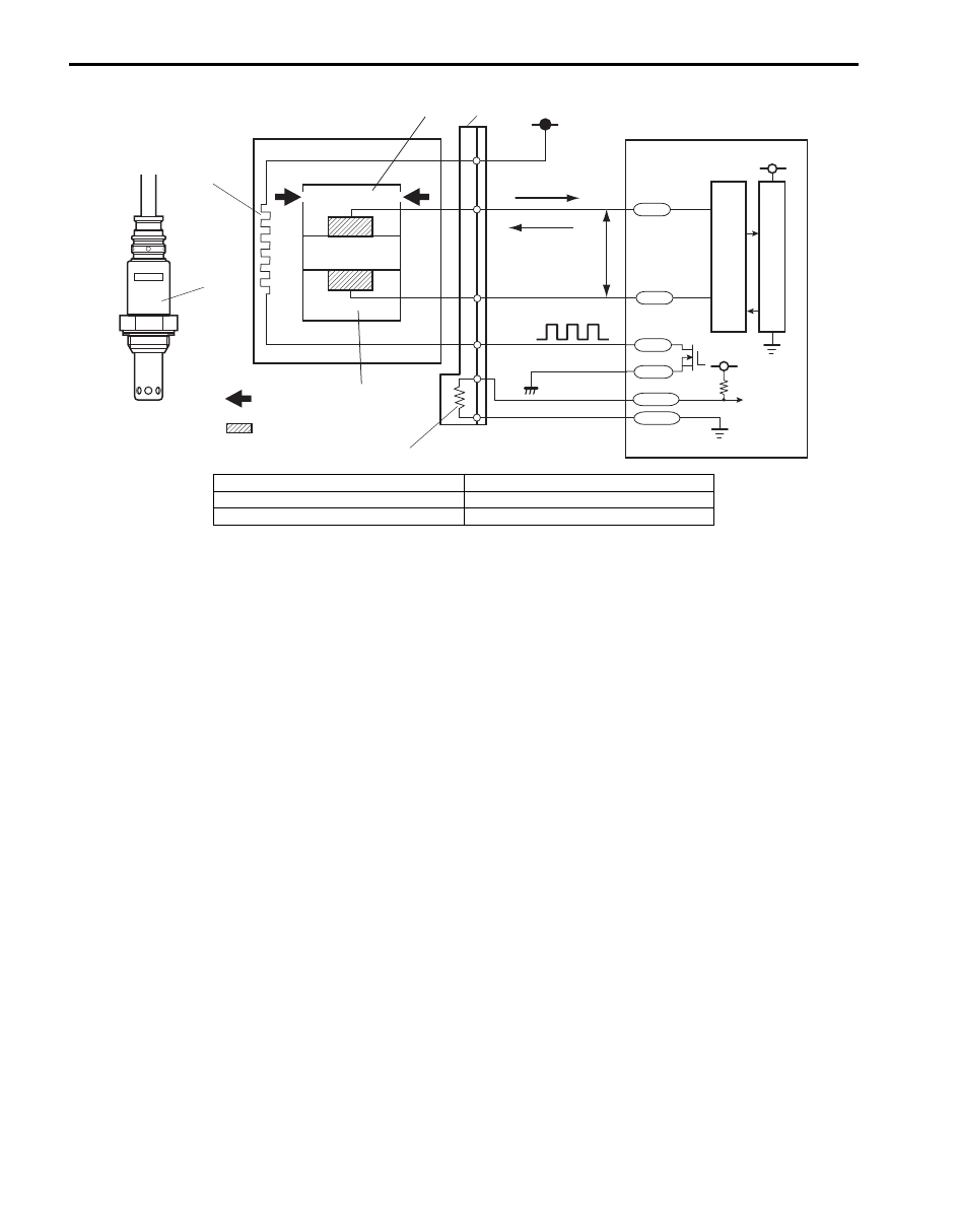
AFS-
AFRV
AFRG
AFH+
AFH-
AFS+
5V
5V
12V
1
1
3
7
8
2
8
9
10
5
11
12
13
14
15
4
I5JB0A110010-02
10. Electrode 13. Lean
11. A/F signal processing circuit
14. Rich
12. CPU 15. 0.4
V
Engine General Information and Diagnosis: 1A-14
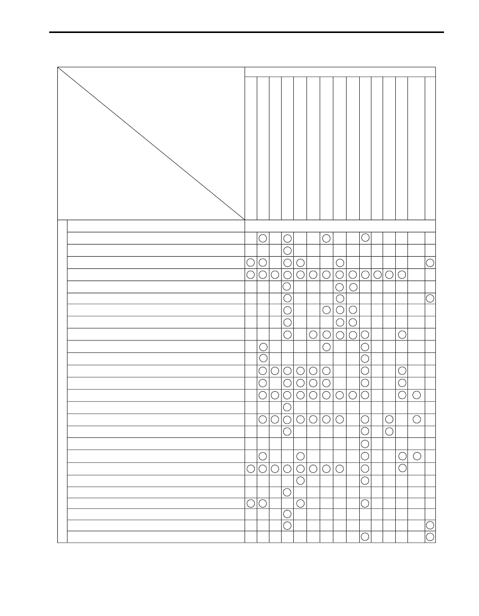
Engine and Emission Control Input / Output Table
S5JB0A1101008
INPUT
OUTPUT
ELECTRIC CONTROL DEVICE
FUEL LEVEL SENSOR
For detecting fuel level
BAROMETRIC PRESSURE SENSOR
STOP LAMP SWITCH
START SWITCH
IGNITION SWITCH
A/C REFRIGERANT PRESSURE SENSOR (if equipped with A/C)
BLOWER SWITCH
A/C SWITCH (if equipped with A/C)
A/C EVAP OUTLET AIR TEMP. SENSOR (if equipped with A/C)
WHEEL SPEED SENSOR
A/F SENSOR
HEATED OXYGEN SENSOR-2
IAT SENSOR OF MAF AND IAT SENSOR
MAF SENSOR OF MAF AND IAT SENSOR
ECT SENSOR
POWER STEERING PRESSURE SWITCH
TP SENSOR
THROTTLE ACTUATOR
FUEL PUMP RELA
Y
FUEL INJECT
IMT VACUUM SOLENOID VALVE
(for J20 engine)
GENERATOR CONTROL
THROTTLE ACTUATOR CONTROL RELAY
OR
A/F SENSOR HEATER & HO2S HEATER
IGNITION COIL
WITH IGNITER
EGR V
A
LV
E
EV
AP CANISTER PURGE
V
A
LV
E
A/C COMPRESSOR RELA
Y (if equipped with A/C)
RADIA
T
OR F
AN RELA
Y
MIL
MAIN RELA
Y
OIL CONTR
OL
V
A
LVE (for M16 engine)
SIGNAL FR
OM SENSOR, SWITCH AND CONTR
OL MODULE
ABS HYDRAULIC UNIT/CONTROL MODULE ASSEMBLY
KNOCK SENSOR
MAP SENSOR
CMP SENSOR
CKP SENSOR
IMMOBILIZER CONTROL MODULE (in ECM) (if equipped)
ELECTRIC LOAD (headlight, rear defogger)
GENERATOR
SHIFT RANGE SWITCH (except "P" or "N" range) (for A/T model)
ACCELERATOR PEDAL POSITION (APP) SENSOR
I5JB0A110014-06
1A-15 Engine General Information and Diagnosis:
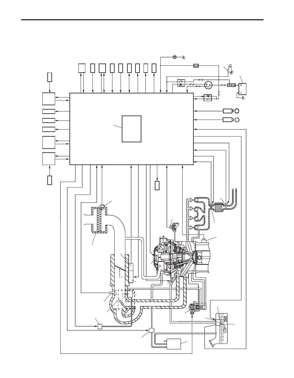
Schematic and Routing Diagram
Engine and Emission Control System Diagram
S5JB0A1102001
48
37
25
42
35
33
34
24
43
18
26
10
9
7
8
14
13
23
11
15
12
2
6
1
3
30
29
38
16
17
36
31
22
21
40
27
41
32
4
28
44
5
45
20
19
46
47
39
49
I5JB0A110015-04
Engine General Information and Diagnosis: 1A-16
1. Air cleaner
18. Radiator cooling fan motor
35. Immobilizer coil antenna (if equipped)
2. EVAP canister purge valve
19. Combination meter
36. Main relay
3. MAF and IAT sensor
20. BCM
37. Wheel speed sensor (VSS)
4. TP sensor
21. Ignition switch
38. Oil control valve (for M16 engine)
5. IMT valve (for J20 engine)
22. Starter magnetic switch
39. TCM (for A/T or model)
6. MAP sensor
23. Heated oxygen sensor (HO2S)-2
40. Starting motor control relay
7. EGR valve
24. DLC
41. A/C refrigerant pressure sensor (if equipped with A/C)
8. EVAP canister
25. Electric load
42. Accelerator pedal position (APP) sensor
9. Tank pressure control valve (built-in fuel pump)
26. Fuel level sensor
43. Throttle actuator control relay
10. Fuel pump
27. Stop lamp
44. Throttle actuator
11. Ignition coil assembly
28. Stop lamp switch
45. IMT vacuum solenoid valve (for J20 engine)
12. Fuel injector
29. ECM
46. Keyless start control module (if equipped)
13. A/F sensor
30. Barometric pressure sensor
47. 4WD control module (for J20 engine)
14. Knock sensor
31. Battery
48. ABS hydraulic unit / control module assembly
15. ECT sensor
32. A/C compressor relay (if equipped
with A/C)
49. For J20 engine
16. CMP sensor
33. Power steering pump pressure
switch
17. CKP sensor
34. Generator
Нет комментариевНе стесняйтесь поделиться с нами вашим ценным мнением.
Текст