Suzuki Grand Vitara JB416 / JB420. Manual — part 204
4C-6 Rear Brakes:
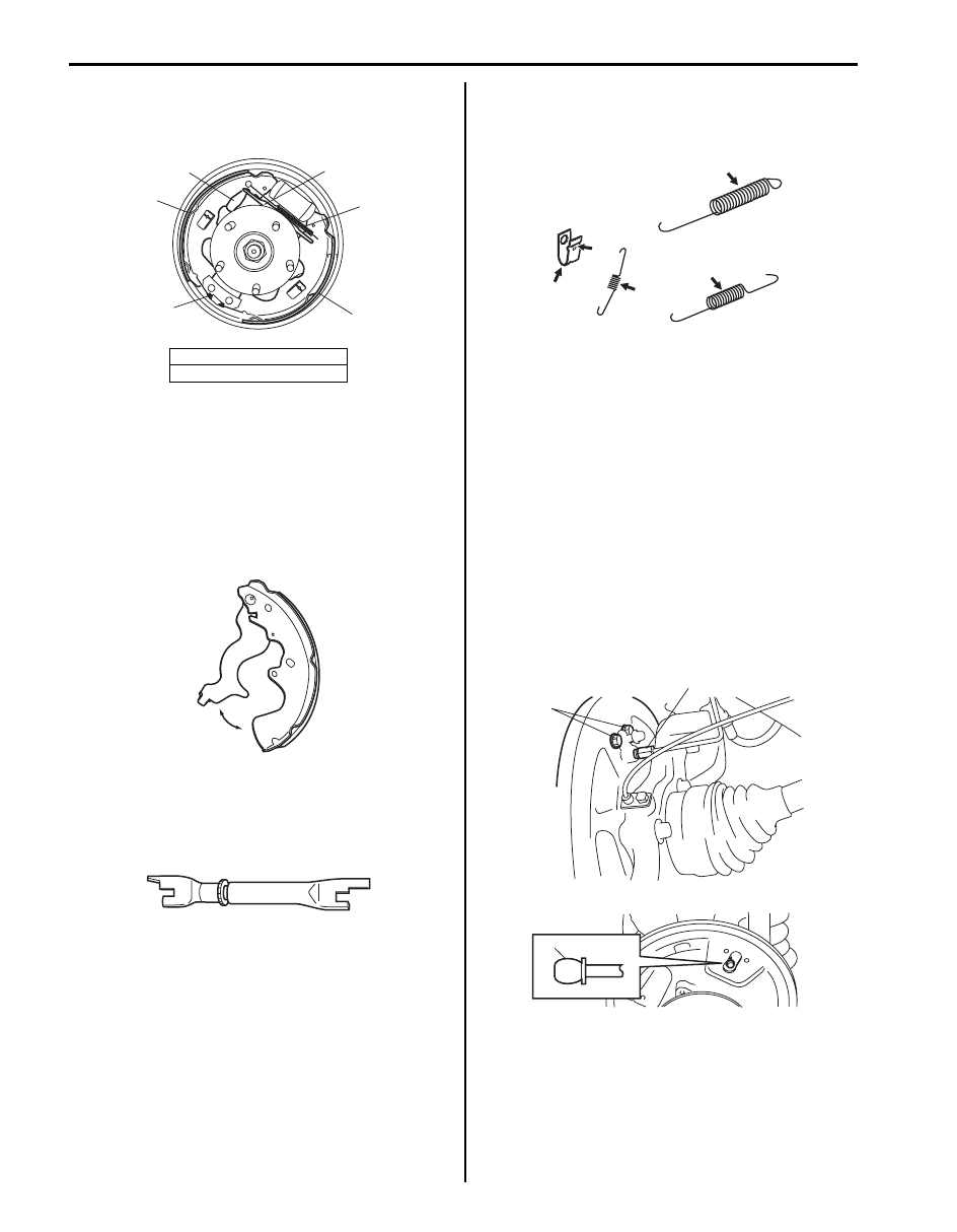
4) Install brake adjuster (2) and upper shoe return
spring (1).
5) Install adjuster pawl lever (3) and adjuster spring.
6) For procedure hereafter, refer to “Rear Brake Drum
Rear Brake Shoe Inspection
S5JB0A4306007
Parking Brake Shoe Lever
Inspect brake shoe lever for free movement against
brake shoe web. If defective, correct or replace.
Brake Adjuster
Check thread or ratchet of adjuster for wear, sticking and
corrosion.
If found defective, replace brake adjuster.
Springs
Inspect for damage or weakening.
Inspect each part with arrow for rust. If found defective,
replace.
Brake Shoe
Refer to “Rear Brake Drum and Shoe Inspection”.
Wheel Cylinder Removal and Installation
S5JB0A4306008
Removal
1) Remove brake drum referring to “Rear Brake Drum
2) Remove brake shoe referring to “Rear Brake Shoe
3) Loosen brake pipe flare nut (1) but only within the
extent that fluid does not leak.
4) Remove wheel cylinder mounting bolts (2).
Disconnect brake pipe from wheel cylinder and put
wheel cylinder bleeder plug cap (3) onto pipe to
prevent fluid from spilling.
4. Brake shoe
5. Lower shoe return spring
3
2
4
1
4
5
I5JB0A430006-01
I5JB0A430009-02
I5JB0A430011-01
I5JB0A430012-02
3
2
1
I5JB0A430013-01

Rear Brakes: 4C-7
Installation
1) Fit wheel cylinder to brake back plate, take off
bleeder plug cap from brake pipe and connect pipe
to wheel cylinder just enough to prevent fluid from
leaking.
2) Tighten wheel cylinder mounting bolts to brake back
plate (1) to specified torque.
Tightening torque
Wheel cylinder mounting bolt (a): 13 N·m (1.3
kgf-m, 9.5 lb-ft)
3) Tighten flare nut of brake pipe (2) to specified torque.
Tightening torque
Brake pipe flare nut (b): 16 N·m (1.6 kgf-m, 12.0
lb-ft)
4) Install bleeder plug cap (3) taken off from pipe back
to bleeder plug.
5) Install brake shoe referring to “Rear Brake Shoe
6) Install brake drum referring to step 1) to 2) of “Rear
Brake Drum Removal and Installation”.
7) Fill reservoir with brake fluid and bleed brake
system. For bleeding operation refer to “Air Bleeding
of Brake System in Section 4A”.
8) Adjust, check brake and install rear wheel referring
to step 3) to 6) of “Rear Brake Drum Removal and
Installation”.
Wheel Cylinder Inspection
S5JB0A4306009
Inspect wheel cylinder disassembled parts for wear,
cracks, corrosion or damage.
NOTE
Clean wheel cylinder components with brake
fluid.
Rear Brake Back Plate Removal and Installation
S5JB0A4306010
Removal
1) Hoist vehicle and remove rear wheel.
2) Uncaulk rear axle nut (1).
3) Pull up parking brake lever fully and remove rear
axle nut (1).
4) Remove brake drum referring to “Rear Brake Drum
5) Remove brake shoe referring to “Rear Brake Shoe
6) Remove wheel cylinder referring to “Wheel Cylinder
7) Remove parking brake cable (1) from brake back
plate by loosening parking cable cap nut (2).
2
(b)
3
(a)
1
I5JB0A430014-01
IYSQ01430019-01
I5JB0A230058-01
2
1
I5JB0A430015-01

4C-8 Rear Brakes:
8) Remove rear wheel hub housing bolts (1).
9) Remove rear wheel hub assembly and brake back
plate from knuckle.
Installation
1) Install brake back plate (1) and rear wheel hub
assembly (2) to knuckle, and tighten wheel hub
housing bolts to specified torque.
Tightening torque
Rear wheel hub housing bolt (a): 50 N·m (5.0
kgf-m, 36.5 lb-ft)
2) Tighten rear axle nut (1) temporarily by hand at this
step.
3) Install parking brake cable (1) to brake back plate
and tighten cable cap nut to specified torque.
Tightening torque
Parking cable cap nut (a): 11 N·m (1.1 kgf-m, 8.0
lb-ft)
4) Install wheel cylinder and rear brake shoe referring
to step 1) to 7) of “Wheel Cylinder Removal and
Installation”.
5) Install brake drum and adjust brake referring to step
1) to 4) of “Rear Brake Drum Removal and
Installation”.
6) Pull up parking brake lever fully and tighten rear axle
nut (1).
Tightening torque
Rear axle nut (a): 220 N·m (22.0 kgf-m, 159.5 lb-
ft)
7) Caulk rear axle nut (1).
8) Install wheel and tighten wheel nuts to specified
torque.
9) Check to ensure that brake drum is free from
dragging and proper braking is obtained. Remove
vehicle from hoist and perform brake test (foot brake
and parking brake).
1
1
I5JB0A230061-01
2
1
(a)
I5JB0A430016-01
1
I5JB0A430017-01
1
(a)
I5JB0A430018-01
I5JB0A230065-01
Rear Brakes: 4C-9
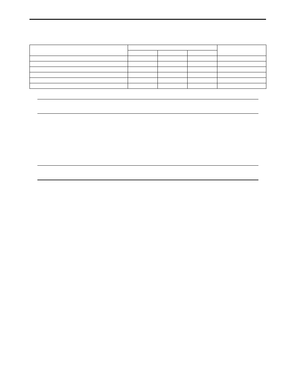
Specifications
Tightening Torque Specifications
S5JB0A4307001
NOTE
The specified tightening torque is also described in the following.
“Rear Drum Brake Assembly Components”
Reference:
For the tightening torque of fastener not specified in this section, refer to “Fastener Information in Section 0A”.
Special Tools and Equipment
Recommended Service Material
S5JB0A4308001
NOTE
Required service material is also described in the following.
“Rear Drum Brake Assembly Components”
Fastening part
Tightening torque
Note
N
⋅m
kgf-m
lb-ft
Wheel nut
100
10.0
72.5
Wheel cylinder mounting bolt
13
1.3
9.5
Brake pipe flare nut
16
1.6
12.0
Rear wheel hub housing bolt
50
5.0
36.5
Parking cable cap nut
11
1.1
8.0
Rear axle nut
220
22.0
159.5
Нет комментариевНе стесняйтесь поделиться с нами вашим ценным мнением.
Текст