Suzuki Grand Vitara JB416 / JB420. Manual — part 366

9B-3 Lighting Systems:
Auto Leveling Headlight System Description (If Equipped)
S5JB0A9201002
Auto Leveling Headlight System adjusts the optical axis of the headlight automatically to be suitable for the varied
vehicle position while the headlights are lit. It consists of front height sensor (1), rear height sensor (2), headlight
leveling control module (3), headlight leveling actuator (4) and headlight leveling warning light (5).
With more passenger(s) or luggage in the vehicle, the vehicle position differs from that in such vehicle state with one
person and no load in the vehicle and angle of the headlight optical axis varies accordingly. This system automatically
adjusts the varied angle to maintain the optical axis properly.
4
2
1
5
3
I5JB0A920036-02
[A]
[A]
[B]
I5JB0A920004-01
[A]: Optical axis of headlight in standard position
[B]: Corrected optical axis of headlight
Lighting Systems: 9B-4
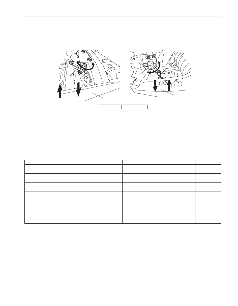
Front and rear height sensors
Height sensor (1) is installed to the front and rear suspension frames respectively and connected to the lower arm (4)
with the link (3). Each height sensor converts vertical movement of the lower arm into the resistance value and outputs
the detected change in the vehicle position as a voltage signal to the headlight leveling control module.
Headlight leveling control module
Headlight leveling control module is installed at the foot of the front passenger seat. It uses the headlight ON signal
from the lighting switch, vehicle speed signal from BCM and vehicle position signal from height sensors to calculate
the angle of the headlight optical axis to be corrected. Then it adjusts the optical axis angle of headlight based on the
calculated angle value by driving the headlight leveling actuator so that proper headlight aiming is obtained. Also,
when any abnormality is detected in the system, the headlight leveling control module makes the headlight leveling
warning light in the combination meter light up to warn the driver of an abnormality in the system.
Fail-safe function of headlight leveling control module
Headlight leveling control module has a fail-safe function which operates as follows.
2
3
1
[A]
[B]
4
2
3
1
4
I5JB0A920005-01
[A]: Front
[B]: Rear
Detecting condition
Fail-safe operation
Warning light
Power voltage supplied to headlight leveling control
module is higher than 18.5V
Stops headlight leveling actuator operation.
OFF
Power voltage supplied to headlight leveling control
module is lower than 9V
Stops headlight leveling actuator operation.
OFF
Vehicle speed is 180km/h or higher
Stops headlight leveling actuator operation.
OFF
Voltage supplied to height sensor is lower than 4.6V
Stops headlight leveling actuator operation.
ON
Signal voltage from height sensor is higher than 4.75V or
lower than 0.25V
Stops headlight leveling actuator operation.
ON
Abnormality in headlight leveling control module is
detected
Resets microcomputer in headlight leveling
control module.
ON
Correction value calculated by headlight leveling control
module exceeds operation range of headlight leveling
actuator
Drives headlight leveling actuator within its
operation range.
OFF
9B-5 Lighting Systems:
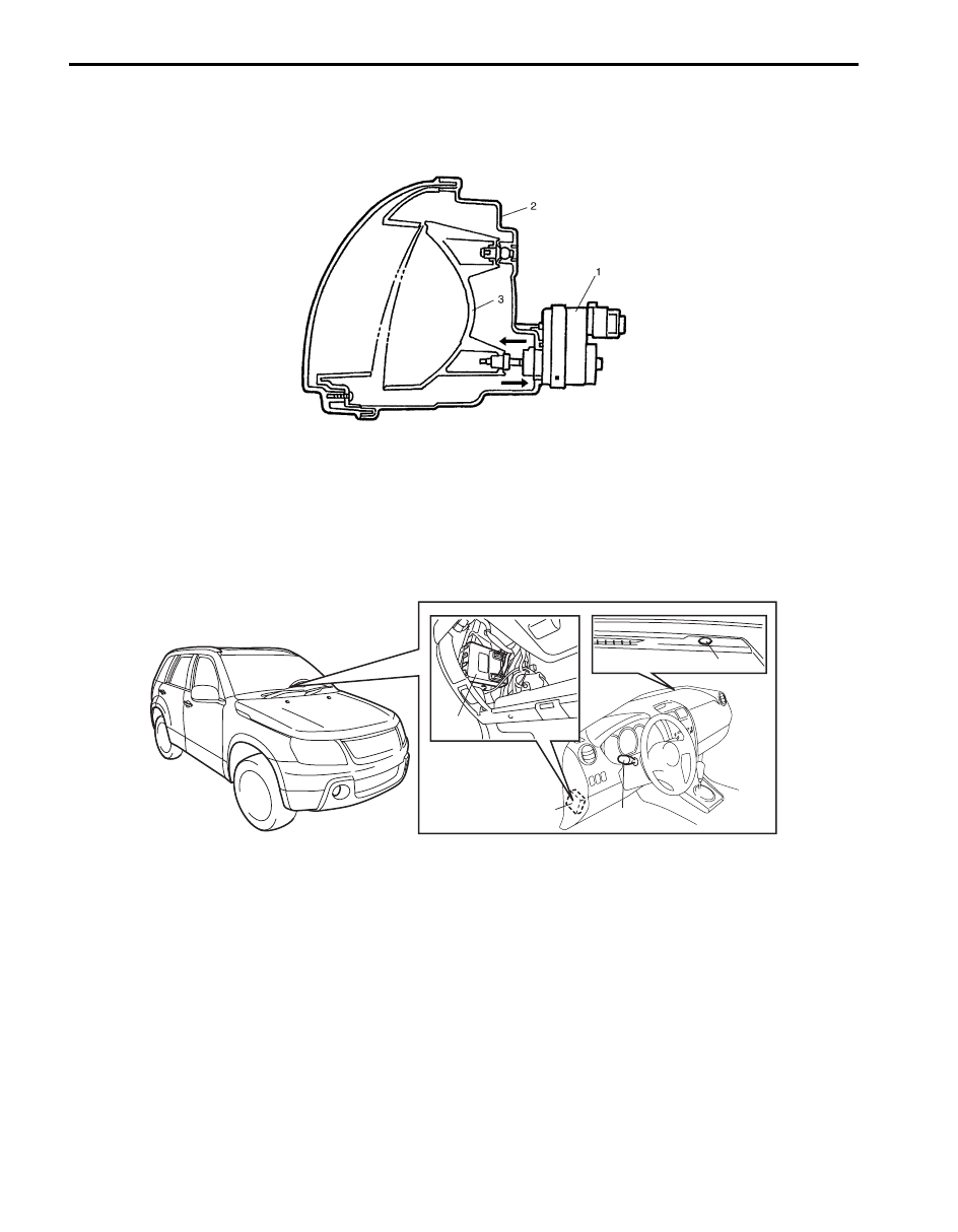
Headlight leveling actuator
Headlight leveling actuator is (1) located in the headlight housing (2). It moves the reflector (3) in the headlight housing
according to the drive signal from the headlight leveling control module so as to adjust the optical axis of the headlight
to the angle calculated by the headlight leveling control module.
Auto-On Headlight System Description (If Equipped)
S5JB0A9201003
The auto-on headlight is controlled by BCM (1) and works as follows.Under such conditions as the ignition switch
turned ON, the lighting switch (2) turned to the “AUTO” position and the parking brake released, when illuminance to
the auto-on headlight sensor (3) becomes lower than the specified value, the headlights and clearance lights are
turned ON by BCM. On the other hand, when illuminance to the auto-on headlight sensor becomes higher than the
specified value under the same conditions, the headlights and clearance lights are turned OFF by BCM.
I5JB0A920006-06
1
1
2
3
I5JB0A920007-01
Lighting Systems: 9B-6
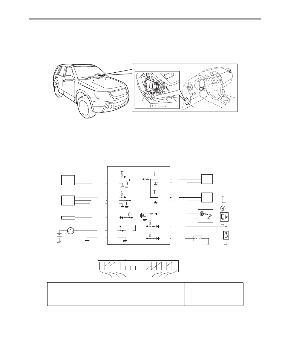
D.R.L. System Description (If Equipped)
S5JB0A9201004
The D.R.L. system is controlled by BCM (1). It lights headlights when following two conditions are met.Conditions for
D.R.L. operation:
• The engine is running
• The lighting switch is at “OFF” position
Schematic and Routing Diagram
Headlight Auto Leveling System wiring Circuit Diagram
S5JB0A9202001
1
1
I5JB0A920008-01
G51-12
G51-19
G51-21
G51-10
G51-23
+B
5V
5V
YEL/RED
GRN/RED
BLK
G51-1
12V
GRN
GRN/YEL
GRN/WHT
YEL
3
G51-13
G51-20
G51-22
5V
BLU/RED
BLU/YEL
BLU/BLK
2
4
5
9
10
11
1
5V
5V
12V
G51-16
G51-3
BLU/BLK
RED/BLU
5V
G51-5 RED/BLU
G51-17
RED
G51-11
G51-24
YEL/GRN
GRN/BLK
6
12V
G51-18
GRN
8
G51-6
G51-9
BLU/WHT
G51
10
11
12
13
16
17
18
19
20
3
1
5
6
9
21
22
23
24
[A]
I5JB0A920011-02
[A]: Headlight leveling control module connector
(viewed from harness side)
4. BCM
8. Headlight leveling warning light
1. Headlight leveling control module
5. Right headlight leveling actuator
9. Ignition switch
2. Front height sensor
6. Left headlight leveling actuator
10. Lighting switch
3. Rear height sensor
7. Combination meter
11. Diagnosis connector
Нет комментариевНе стесняйтесь поделиться с нами вашим ценным мнением.
Текст