Suzuki Grand Vitara JB416 / JB420. Manual — part 182
3C-42 Transfer: Motor-Shift Type (Transfer with Shift Actuator)
DTC C1240: 4WD Control Module Power Supply Circuit Malfunction
S5JB0A3314050
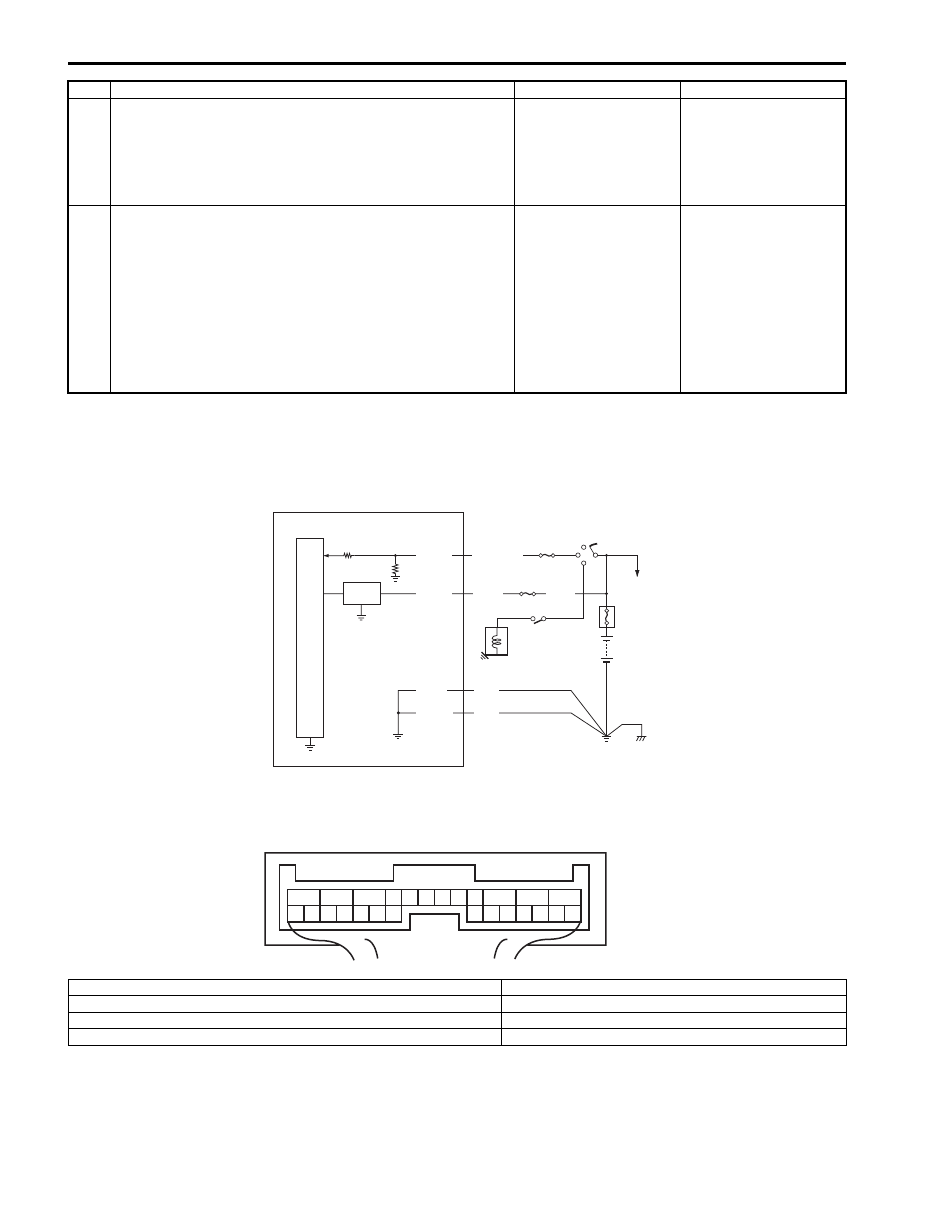
Wiring Diagram
3
Center differential lock switch check
1) Check center differential lock switch referring to
“Transfer Assembly Inspection: Motor-Shift Type
(Transfer with Shift Actuator)”.
Is switch in good condition?
Substitute a known-
good 4WD control
module and recheck.
Replace center
differential lock switch.
4
Wire harness check
1) Disconnect connector from 4WD control module
connector “E91” with ignition switch OFF.
2) Check for proper connection to “E91-14” terminal of
4WD control module connector.
3) If OK, measure resistance between “RED/GRN” terminal
of center differential lock switch connector and “E91-14”
terminal of 4WD control module connector.
Is it 1 M
Ω
or more?
Substitute a known-
good 4WD control
module and recheck.
“RED/GRN” wire is
shorted to ground
circuit.
Step
Action
Yes
No
5V
+BB
E91-12
E91-11
E91-10
E91-1
BLK
BLK
WHT
BLK/WHT
2
4
6
3
5
7
1
1
2
3
4
5
6
7
8
9
10
11
12
13
14
15
16
17
18
19
20
21
22
23
24
25
26
[A]
BLK
I5JB0A332019-01
[A]: 4WD control module connector “E91” (viewed from harness side)
4. “4WD” fuse
1. 4WD control module
5. Shift switch (for A/T model) or CPP switch (for M/T model)
2. “IG COIL” fuse
6. Main fuse box
3. Ignition switch
7. Starting motor

Transfer: Motor-Shift Type (Transfer with Shift Actuator) 3C-43
DTC Detecting Condition and Trouble Area
DTC Confirmation Procedure
1) Clear DTC using scan tool.
2) Start engine and drive vehicle at 30 km/h (19 mph) or more vehicle speed at least for 1 min.
3) Stop vehicle and check DTC.
Troubleshooting
DTC C1243: Internal Circuit Malfunction of 4WD Control Module
S5JB0A3314056
DTC Detecting Condition and Trouble Area
DTC Confirmation Procedure
1) Clear DTC using scan tool.
2) Turn ignition switch to ON position for 60 seconds.
3) Check DTC.
Troubleshooting
Substitute a known-good 4WD control module and recheck.
DTC detecting condition
Trouble area
4WD control module power supply voltage is out of specification
while vehicle is running at 20 km/h (12 mph) or more.
• 4WD control module power supply circuit
Step
Action
Yes
No
1
Was “4WD control system check” performed?
Go to Step 2.
Go to “4WD Control
System Check: Motor-
Shift Type (Transfer with
Shift Actuator)”.
2
4WD control module power circuit check
1) Disconnect 4WD control module connector with ignition
switch OFF.
2) Check for proper connection to “E91” terminal of 4WD
control module connector.
3) If connection is OK, measure voltage between “E91-11”
terminal of 4WD control module connector and vehicle
body ground with ignition switch ON.
Is it 10 – 14 V?
Poor “E91-11”
connection or
intermittent trouble.
Check for intermittent
referring to “Intermittent
and Poor Connection
Inspection in Section
00”. If wire and
connections are OK,
substitute a known-
good 4WD control
module and recheck.
“4WD” fuse blown,
“WHT” or “BLK” wire is
circuit open or circuit
short.
DTC detecting condition
Trouble area
EEPROM Error
• 4WD control module
3C-44 Transfer: Motor-Shift Type (Transfer with Shift Actuator)
DTC C1246: Clutch Pedal Position (CPP) Switch Circuit Short
S5JB0A3314051
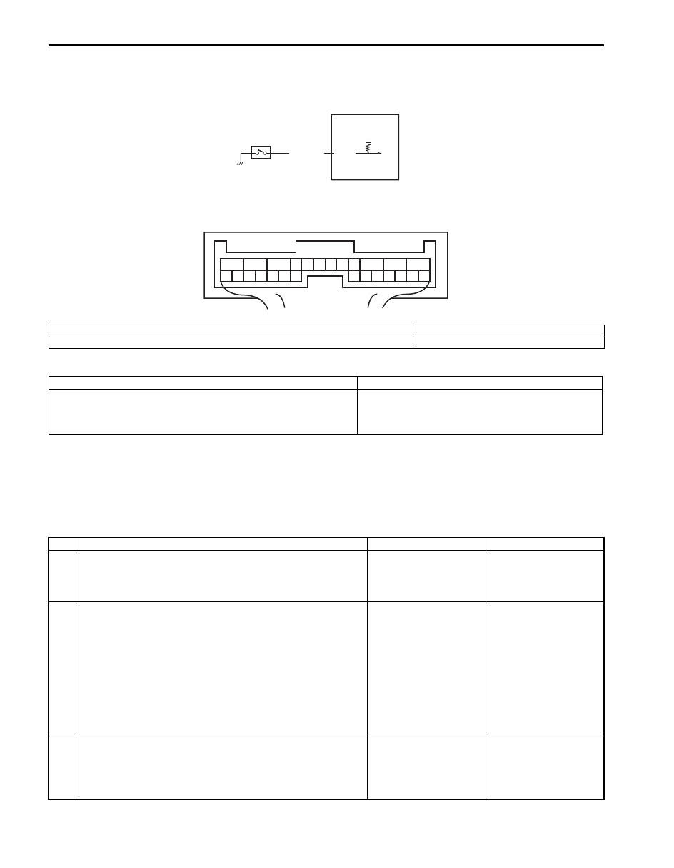
Wiring Diagram
DTC Detecting Condition and Trouble Area
DTC Confirmation Procedure
1) Clear DTC using scan tool.
2) Start engine and drive vehicle at 50 km/h (31 mile/h) or more vehicle speed at least for 1 min.
3) Stop vehicle and check DTC.
Troubleshooting
12V
E91-7
BLK/ORN
1
2
1
2
3
4
5
6
7
8
9
10
11
12
13
14
15
16
17
18
19
20
21
22
23
24
25
26
[A]
I5JB0A332020-01
[A]: 4WD control module connector “E91” (viewed from harness side)
2. 4WD control module
1. CPP switch
DTC detecting condition
Trouble area
CPP switch signal is input when vehicle speed is 30 km/h (19
mph).
• CPP switch
• CPP switch circuit
• 4WD control module
Step
Action
Yes
No
1
Was “4WD control system check” performed?
Go to Step 2.
Go to “4WD Control
System Check: Motor-
Shift Type (Transfer with
Shift Actuator)”.
2
CPP switch circuit check
1) Disconnect CPP switch connector with ignition switch
OFF.
2) Check for proper connection to terminal of CPP switch
connector.
3) If connection is OK, measure voltage between “BLK/
ORN” terminal of CPP switch connector and vehicle
body ground with ignition switch ON.
Is it 10 – 14 V?
Go to Step 3.
Go to Step 4.
3
CPP switch check
1) Check CPP switch referring to “Clutch Pedal Position
(CPP) Switch Inspection and Adjustment in Section 5C”.
Is switch in good condition?
Substitute a known-
good 4WD control
module and recheck.
Replace CPP switch.
Transfer: Motor-Shift Type (Transfer with Shift Actuator) 3C-45
DTC U1073: Control Module Communication Buss Off
S5JB0A3314052
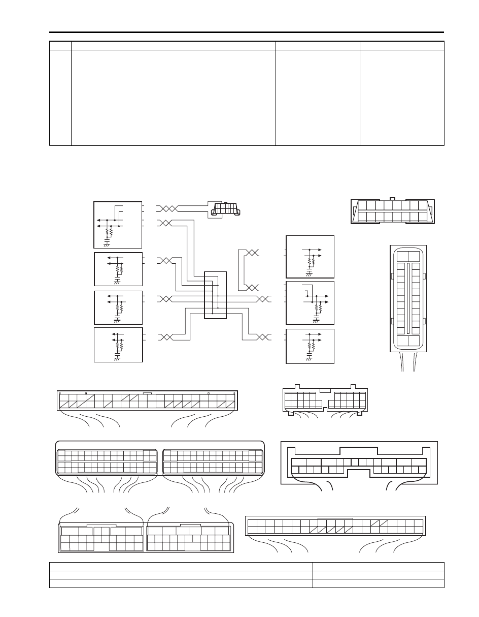
Wiring Diagram
4
Wire harness check
1) Disconnect connector from 4WD control module
connector “E91” with ignition switch OFF.
2) Check for proper connection to “E91-7” terminal of 4WD
control module connector.
3) If OK, measure resistance between “BLK/ORN” terminal
of CPP switch connector and “E91-7” terminal of 4WD
control module connector.
Is it 1 M
Ω
or more?
Substitute a known-
good 4WD control
module and recheck.
“BLK/ORN” wire is
shorted to ground
circuit.
Step
Action
Yes
No
WHT
RED
WHT
RED
G44-18
G44-19
G44
[A]
[B]
[C]
[G]
1
2
3
4
5
6
7
8
9
10
11
14
15
16
36
34 33 32 31 30 29
24 23
37
18
19
20
G28-8
G28-10
WHT/BLU
WHT/BLU
WHT/RED
WHT/RED E23-4
E23-19
WHT
RED E03-12
E03-10
E03-6
E03-8
WHT
RED
E92-17
E92-7
WHT
RED
E91-22
E91-23
WHT
RED
G31-1
G31-3
6
5
16 15 14 13 12 11
4 3
24 23
21
22
10 9
8
7
2
1
19
20
18 17
E92
17 16
26 25
15 14
6
5
3
4
2
13 12
23 22
24
11 10 9
21 20 19
8 7
18
1
E93
2 1
E23
C37
3
4
18
19
5
6
7
10
11
17
20
47 46
49
50
51
21
22
52
16
25
9
24
14
29
55
57
5453
59
60
58
2
26
27
28
15
30
56
48
32 31
34
35
36
37
40
42
3938
44
45
43
41
33
1
12
13
23
8
3
4
18
19
5
6
7
10
11
17
20
47 46
49
50
51
21
22
52
16
25
9
24
14
29
55
57
5453
59
60
58
26
27
28
15
30
56
48
32 31
34
35
36
37
40
42
3938
44
45
43
41
33
12
13
23
8
1
2
3
4
5
6
7
8
9
10
11
17
1615141312
2221201918
G28
[E]
G31
1
2
3
4
7
8
9
10
11
14
15
16
36
34
35
24 23
21
22
28 27
25
26
37
39 38
40
18 17
13 12
19
20
[D]
E03
15
16
17
18
19
20
21
22
23
24
25
2
3
4
5
6
7
8
9
10
11
12
1
13
14
26
1
2
3
4
5
6
7
8
9
10
11
12
13
14
15
16
17
18
19
20
21
22
23
24
25
26
[F]
E91
WHT
RED
G31-2
G31-4
[H]
8
7
6
5
4
3
2
1
9
10
11
12
13
14
15
16
1
2
3
4
8
5
6
7
I5JB0A332021-01
[A]: Keyless start control module connector (if equipped) (viewed from harness side)
1. BCM
[B]: ECM connector (viewed from harness side)
2. 4WD control module
[C]: TCM connector (for A/T model) (viewed from harness side)
3. TCM (for A/T model)
Нет комментариевНе стесняйтесь поделиться с нами вашим ценным мнением.
Текст