Suzuki Grand Vitara JB416 / JB420. Manual — part 265
6B-8 Steering Wheel and Column:
Removal
WARNING
!
Never rest a steering column assembly on
the steering wheel with air bag (inflator)
module face down and column vertical.
Otherwise personal injury may result.
CAUTION
!
Never turn steering wheel while steering
column with steering wheel is removed.
Turning steering wheel more than about two
and a half turns will break contact coil cable
assembly.
1) Disconnect negative (–) cable at battery.
2) Disable air bag system referring to “Disabling Air
3) Remove steering wheel and contact coil cable
assembly. Refer to “Steering Wheel Removal and
Installation” and “Contact Coil Cable Assembly
Removal and Installation”.
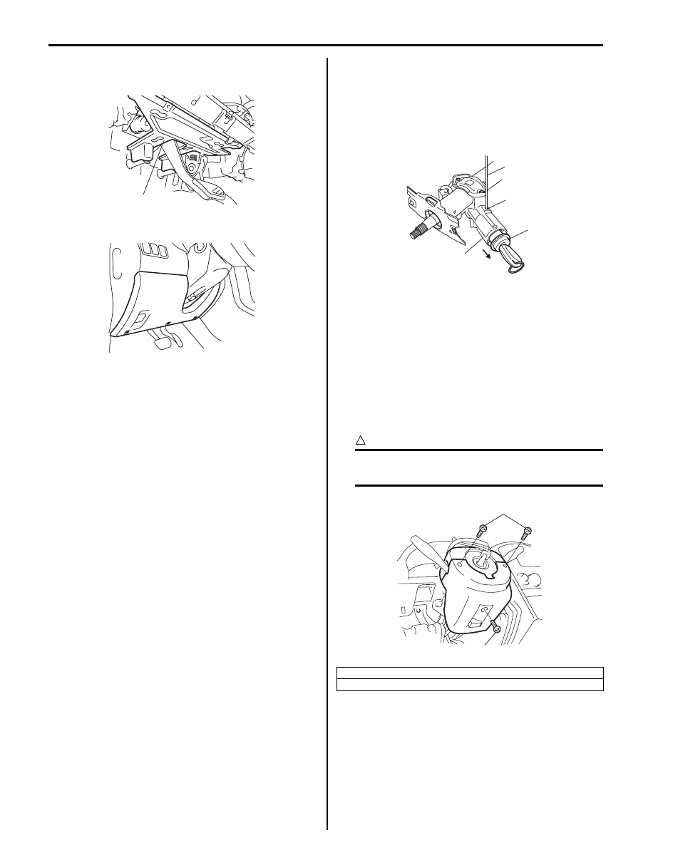
4) Remove instrument panel under cover (1) from
instrument panel.
5) Remove immobilizer control module (ICM) referring
to “Immobilizer Control Module (ICM) Removal and
Installation in Section 10C”.
6) Remove lighting switch referring to “Headlight Switch
(in Lighting Switch) Removal and Installation in
Section 9B”.
7) Remove washer switch referring to “Windshield
Wiper and Washer Switch Removal and Installation
in Section 9D”.
8) Disconnect connector from steering lock assembly.
9) For A/T vehicle, disconnect shift (key) interlock cable
(1) from ignition switch with ignition switch turned at
ACC position.
After disconnecting, turn ignition switch to LOCK
position.
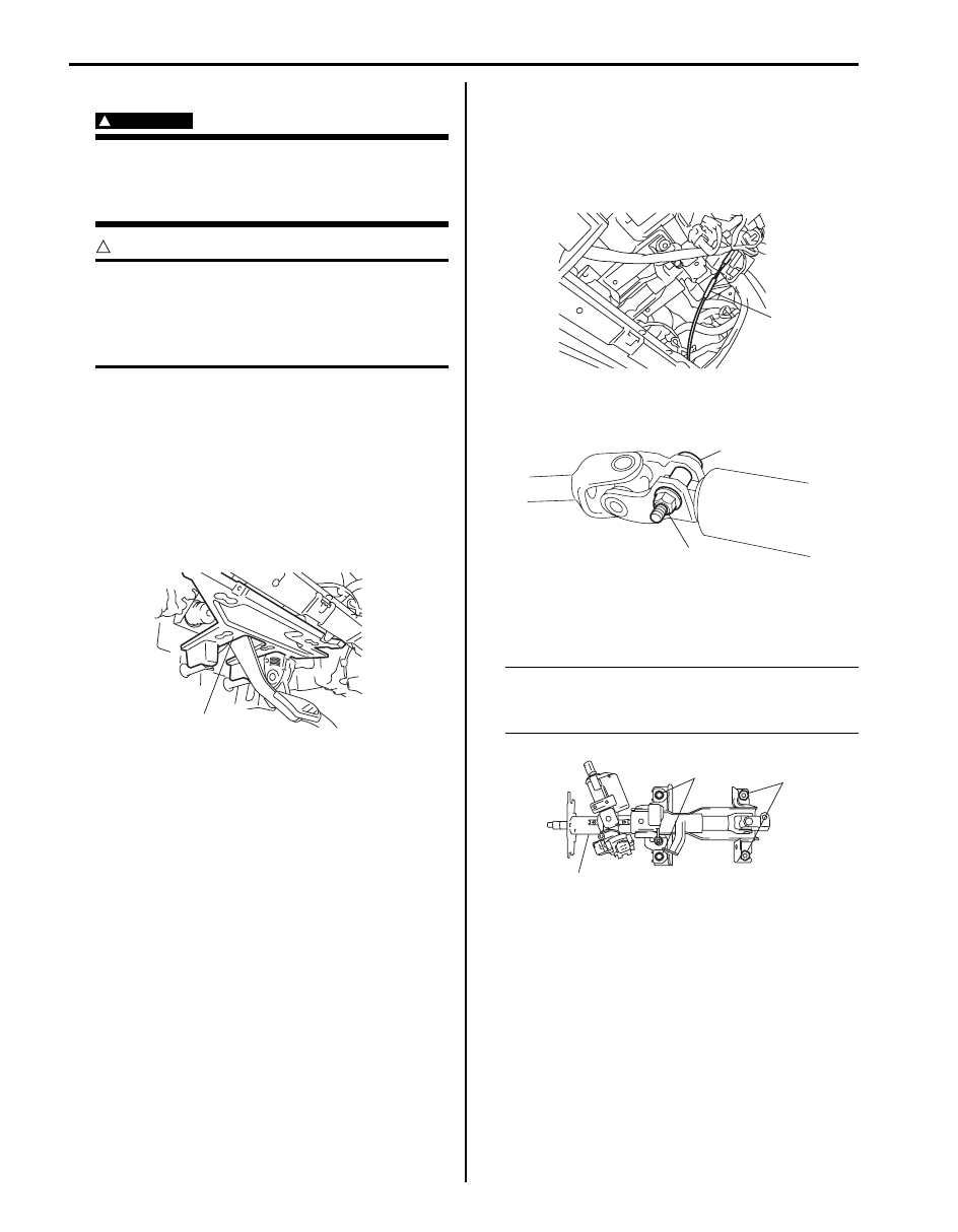
10) Remove steering upper shaft upper joint bolt (1) and
nut (2).
11) Remove column support bracket. (if equipped)
12) Remove steering column assembly (1) mounting
bolts (2) and nuts (3).
NOTE
Tilt lever should not be moved before
mounting bolts and nuts are tighten
completely.
13) Remove steering column assembly from vehicle.
1
I5JB0A620018-01
1
I5JB0A620019-01
1
2
I5JB0A620020-01
1
2
3
I5JB0A620021-01
Steering Wheel and Column: 6B-9
Installation
CAUTION
!
After tightening steering column assembly
mounting bolts and nuts, steering shaft joint
bolts should be tightened.
1) Be sure that front wheels and steering wheel are in
straight-ahead position.
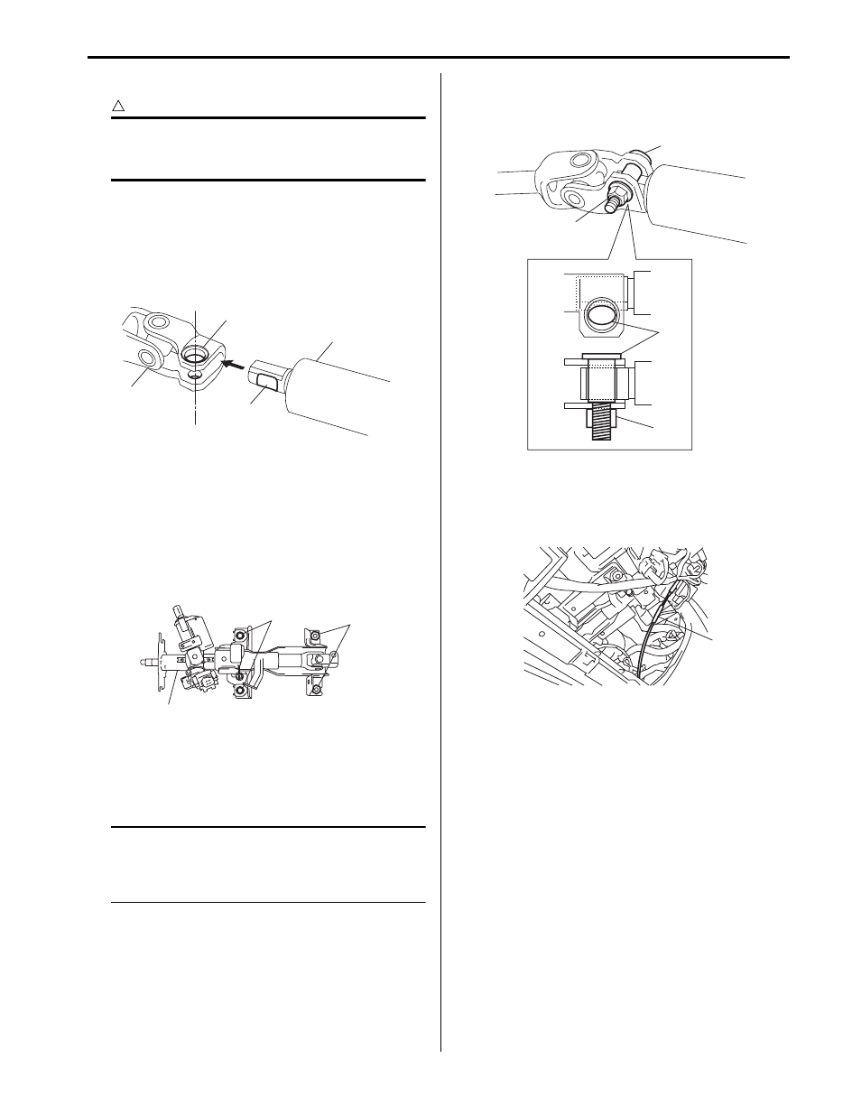
2) Align flat part “A” of steering upper shaft upper joint
(1) with bolt hole “B” of steering column assembly (2)
as shown in the figure. Then connect steering upper
shaft upper joint.
3) Install steering column assembly (1) with contacting
upper side of lower bracket slits to mounting bolts.
Tighten steering column upper mounting nuts (3) first
and then lower mounting bolts (2) to specified
torque.
Tightening torque
Steering column assembly mounting bolt and
nut (a): 25 N·m (2.5 kgf-m, 18.0 lb-ft)
4) Install column support bracket. (if equipped)
5) Install new steering upper shaft upper joint bolt (2)
and nut (1). Tighten new steering upper shaft upper
joint nut (1) to specified torque.
NOTE
Do not reuse steering upper shaft upper joint
bolt and nut.
Be sure to use new bolt and nut when
installing.
Tightening torque
Steering upper shaft assembly upper joint nut
(a): 23 N·m (2.3 kgf-m, 17.0 lb-ft)
6) For A/T vehicle, connect shift (key) interlock cable
(1) to ignition switch with ignition switch turned at
ACC position.
And then turn ignition switch LOCK position.
7) Connect steering lock assembly connector.
8) Install contact coil cable assembly referring to
“Contact Coil Cable Assembly Removal and
Installation”.
9) Install washer switch referring to “Windshield Wiper
and Washer Switch Removal and Installation in
Section 9D”.
10) Install lighting switch referring to “Headlight Switch
(in Lighting Switch) Removal and Installation in
Section 9B”.
11) Install immobilizer control module (ICM) referring to
“Immobilizer Control Module (ICM) Removal and
Installation in Section 10C”.
2
“A”
“B”
1
I5JB0A620022-01
1
2, (a)
3, (a)
I5JB0A620023-01
2
2
1, (a)
1, (a)
I5JB0A620024-01
1
I5JB0A620019-01
6B-10 Steering Wheel and Column:
12) Install instrument panel under cover (1) to instrument
panel.
13) Install steering column hole cover (1).
14) If steering wheel is removed, install it by referring to
“Steering Wheel Removal and Installation”.
15) Connect negative (–) cable to battery.
16) After installing steering column assembly, be sure to
enable air bag system by referring to “Enabling Air
Bag System in Section 8B”.
Steering Column Assembly Inspection
S5JB0A6206007
Check steering column for damage and operation
referring to “Checking Steering Column for Accident
Damage”.
Ignition Switch Cylinder Assembly Removal
and Installation (Without Keyless Start System)
S5JB0A6206015
Removal
1) Disconnect negative (–) cable at battery.
2) Disable air bag system referring to “Disabling Air
3) Remove steering column upper and lower covers.
4) Remove immobilizer control module referring to
“Immobilizer Control Module (ICM) Removal and
Installation in Section 10C”.
5) Remove ignition switch cylinder assembly as follows.
a) Turn ignition key to “ACC” position.
b) Insert 2 mm (0.078 in.) rod (2) through hole (3)
and push ignition switch cylinder lock.
c) Detach ignition switch cylinder assembly (1) from
steering lock assembly (4).
Installation
1) Install ignition switch cylinder assembly as follows.
a) Turn ignition key to “ACC” position.
b) In this state, push ignition switch cylinder
assembly into steering lock assembly till it clicks.
2) Install immobilizer control module (ICM) referring to
“Immobilizer Control Module (ICM) Removal and
Installation in Section 10C”.
3) Install upper and lower cover and screws (1).
CAUTION
!
When installing covers, be careful so that
each lead wire is not caught between covers.
4) Enabling air bag system referring to “Disabling Air
1
I5JB0A620018-01
1
I5JB0A620011-01
*: Standard screw
**: Tapping screw
2
3
1
4
I5JB0A620025-01
1*
1**
I5JB0A620026-01
Steering Wheel and Column: 6B-11
Steering Lock Assembly (Ignition Switch)
Removal and Installation
S5JB0A6206008
Removal
1) Remove steering column assembly. Refer to
“Steering Column Assembly Removal and
Installation”.
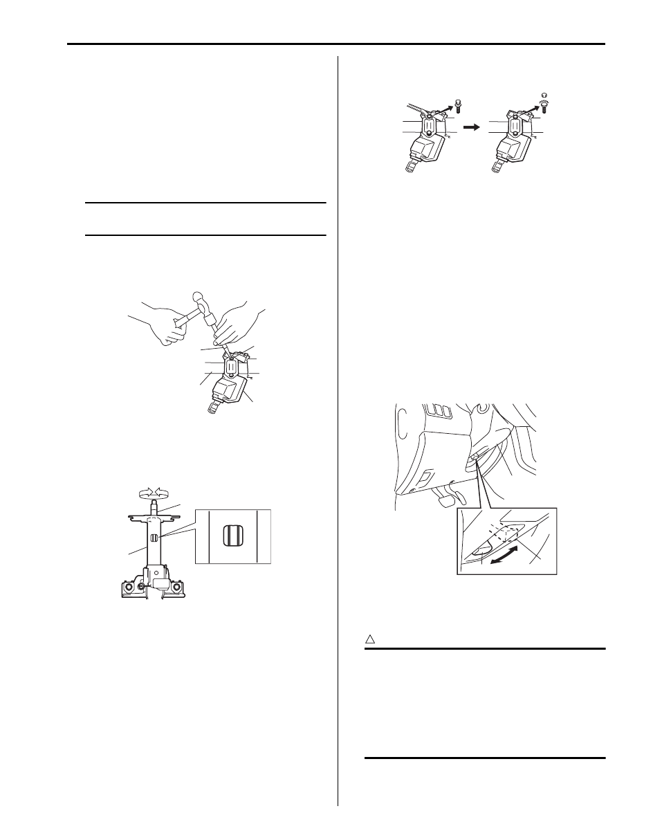
2) Using center punch (with sharp point) (1) as shown
in the figure, loosen and remove steering lock
mounting bolts (2).
NOTE
Use care not to damage aluminum part of
steering lock body (3) with center punch (1).
3) Turn ignition key to ACC or ON position and remove
steering lock assembly (3) from steering column
assembly (4).
Installation
1) Position oblong hole of steering shaft (2) in the
center of hole in steering column assembly (1).
2) Turn ignition key to ACC or ON position and install
steering lock assembly onto column.
3) Now turn ignition key to LOCK position and pull it
out.
4) Align hub on lock with oblong hole of steering shaft
and rotate shaft to assure that steering shaft is
locked.
5) Tighten new bolts until head of each bolt is broken
off.
6) Turn ignition key to ACC or ON position and check to
be sure that steering shaft rotates smoothly. Also
check for lock operation.
7) Install steering column. Refer to “Steering Column
Assembly Removal and Installation”.
Adjustable Steering Column Release Lever
Inspection
S5JB0A6206009
Check to make sure that the followings:
• Steering column (1) moves smoothly when adjustable
steering column release lever is at upper position (2)
(i.e., steering column is not locked).
• Steering column (1) is fixed securely when adjustable
steering column release lever is at lower position (3)
(i.e., steering column is locked).
Steering Upper Shaft Assembly Removal and
Installation
S5JB0A6206010
CAUTION
!
Never turn steering wheel while steering
upper shaft assembly is removed.
Should it have been turned and contact coil
cable assembly have got out of its centered
position, it needs to be centered again. Also,
turning steering wheel more than about two
and a half turns will break contact coil cable
assembly.
1
2
4
3
I5JB0A620027-01
2
1
I5JB0A620028-01
I5JB0A620029-01
1
2
3
I5JB0A620030-01
Нет комментариевНе стесняйтесь поделиться с нами вашим ценным мнением.
Текст