Suzuki Grand Vitara JB416 / JB420. Manual — part 13

1A-1 Engine General Information and Diagnosis:
Engine
Engine General Information and Diagnosis
Precautions
Precautions on Engine Service
S5JB0A1100001
CAUTION
!
The following information on engine service
should be noted carefully, as it is important in
preventing damage, and in contributing to
reliable engine performance.
• When raising or supporting engine for any reason, do
not use a jack under oil pan. Due to small clearance
between oil pan and oil pump strainer, jacking against
oil pan may cause it to be bent against strainer,
resulting in damaged oil pick-up unit.
• It should be kept in mind, while working on engine,
that 12-volt electrical system is capable of violent and
damaging short circuits.
When performing any work where electrical terminals
can be grounded, ground cable of the battery should
be disconnected at battery.
• Any time the air cleaner, throttle body or intake
manifold is removed, the intake opening should be
covered. This will protect against accidental entrance
of foreign material which could follow intake passage
into cylinder and cause extensive damage when
engine is started.
Precautions in Diagnosing Trouble
S5JB0A1100002
• Don’t disconnect couplers from ECM, battery cable
from battery, ECM ground wire harness from engine
or main fuse before confirming diagnostic information
(DTC, freeze frame data, etc.) stored in ECM memory.
Such disconnection will erase memorized information
in ECM memory.
• Diagnostic information stored in ECM memory can be
cleared as well as checked by using SUZUKI scan
tool or OBD generic scan tool (Vehicle without
diagnosis connector). Before using scan tool, read its
Operator’s (Instruction) Manual carefully to have good
understanding as to what functions are available and
how to use it.
It is indistinguishable which module turns on MIL
because not only ECM but also TCM (for A/T model)
turns on MIL (For details of on-board diagnostic
system for A/T model, refer to “On-Board Diagnostic
System Description in Section 5A”. Therefore, check
both ECM and TCM (for A/T model) for DTC when
MIL lights on.
When checking ECM for DTC, keep in mind that DTC
is displayed on the scan tool as follows depending on
the scan tool used.
– SUZUKI scan tool displays DTC detected by ECM.
– OBD generic scan tool displays DTC detected by
each of ECM and TCM (for A/T model)
simultaneously.
• Priorities for diagnosing troubles
If two or more DTCs are stored, proceed to the DTC
flow which has been detected earliest in the order and
follow the instruction in that flow.
If no instructions are given, troubleshoot DTCs
according to the following priorities.
a. DTCs other than DTC P0171 / P0172 (Fuel
system too lean / too rich), DTC P0300 / P0301 /
P0302 / P0303 / P0304 (Misfire detected) and
DTC P0401 / P0402 (EGR flow malfunction)
b. DTC P0171 / P0172 (Fuel system too lean / too
rich) and DTC P0401 / P0402 (EGR flow
malfunction)
c. DTC P0300 / P0301 / P0302 / P0303 / P0304
(Misfire detected)
• Be sure to read “Precautions for Electrical Circuit
Service in Section 00” before inspection and observe
what is written there.
• ECM replacement:
When substituting a known-good ECM, check for the
following conditions. Neglecting this check may cause
damage to a known-good ECM.
– Resistance value of all relays, actuators is as
specified respectively.
– MAP sensor, electric load current sensor (for J20
engine), A/C refrigerant pressure sensor (if
equipped with A/C), accelerator pedal position
(APP) sensor, TP sensor and CO adjust resistor (if
not equipped with A/F sensor) are in good condition
and none of power circuits of these sensors is
shorted to ground.
• Communication of ECM, BCM, combination meter,
keyless start control module (if equipped) ABS
hydraulic unit / control module assembly, 4WD control
module (for J20 engine) and TCM (for A/T model), is
established by CAN (Controller Area Network). (For
more detail of CAN communication for ECM, refer to
“CAN Communication System Description”).
Therefore, handle CAN communication line with care
referring to “Precaution for CAN Communication
System in Section 00”.
• Immobilizer transponder code registration after
replacing ECM
When ECM is replaced with new one or with another
one, make sure to register immobilizer transponder
code to ECM correctly according to “Procedure after
ECM Replacement in Section 10C”.
Engine General Information and Diagnosis: 1A-2
Precautions For DTC Troubleshooting
S5JB0A1100005
• Before performed trouble shooting, be sure to read
the “Precautions of ECM Circuit Inspection”.
• When measuring circuit voltage, resistance and/or
pulse signal at ECM connector, connect the special
tool to ECM and/or the ECM connectors referring to
“Inspection of ECM and Its Circuits”.
• Upon completion of inspection and repair work,
perform “DTC Confirmation Procedure” and confirm
that the trouble has been corrected.
Precautions of ECM Circuit Inspection
S5JB0A1100003
• ECM connectors are waterproofed. Each terminal of
the ECM connectors is sealed up with the grommet.
Therefore, when measuring circuit voltage, resistance
and/or pulse signal at ECM connector, do not insert
the tester’s probe into the sealed terminal at the
harness side. When measuring circuit voltage,
resistance and/or pulse signal at ECM connector,
connect the special tool to the ECM connectors. And,
insert the tester’s probe into the special tool’s
connectors at the harness side, and then measure
voltage, resistance and/or pulse signal. Or, ECM and
its circuits may be damaged by water.
• Wire colors of the special tool’s connectors are
different from the ones of the ECM connectors.
However, the circuit arrangement of the special tool’s
connectors is same as the one of the ECM
connectors. Therefore, measure circuit voltage and
resistance by identifying the terminal location subject
to the measurement.
Precautions of Electric Throttle Body System
Calibration
S5JB0A1100004
After performing one of works described below, it is
necessary to re-register the completely closed throttle
valve reference position stored in memory of ECM. (For
detailed information, refer to “Description of Electric
Throttle Body System Calibration”.) For the procedure to
register such data in ECM, refer to “Electric Throttle
Body System Calibration in Section 1C”.
• To shut off backup power of ECM for such purposes of
battery replacement or “DOME” fuse removal
• To erase DTCs P0122, P0123, P0222, P0223, P2101,
P2102, P2103, P2111, P2119 and/or P2135
• To replace ECM
• To replace throttle body and/or accelerator pedal
position (APP) sensor assembly
General Description
Statement on Cleanliness and Care
S5JB0A1101001
An automobile engine is a combination of many
machined, honed, polished and lapped surfaces with
tolerances that are measured in the thousands of an
millimeter (ten thousands of an inch).
Accordingly, when any internal engine parts are
serviced, care and cleanliness are important.
It should be understood that proper cleaning and
protection of machined surfaces and friction areas is part
of the repair procedure. This is considered standard
shop practice even if not specifically stated.
• A liberal coating of engine oil should be applied to
friction areas during assembly to protect and lubricate
the surfaces on initial operation.
• Whenever valve train components, pistons, piston
rings, connecting rods, rod bearings, and crankshaft
journal bearings are removed for service, they should
be retained in order.
At the time of installation, they should be installed in
the same locations and with the same mating
surfaces as when removed.
• Battery cables should be disconnected before any
major work is performed on the engine.
Failure to disconnect cables may result in damage to
wire harness or other electrical parts.
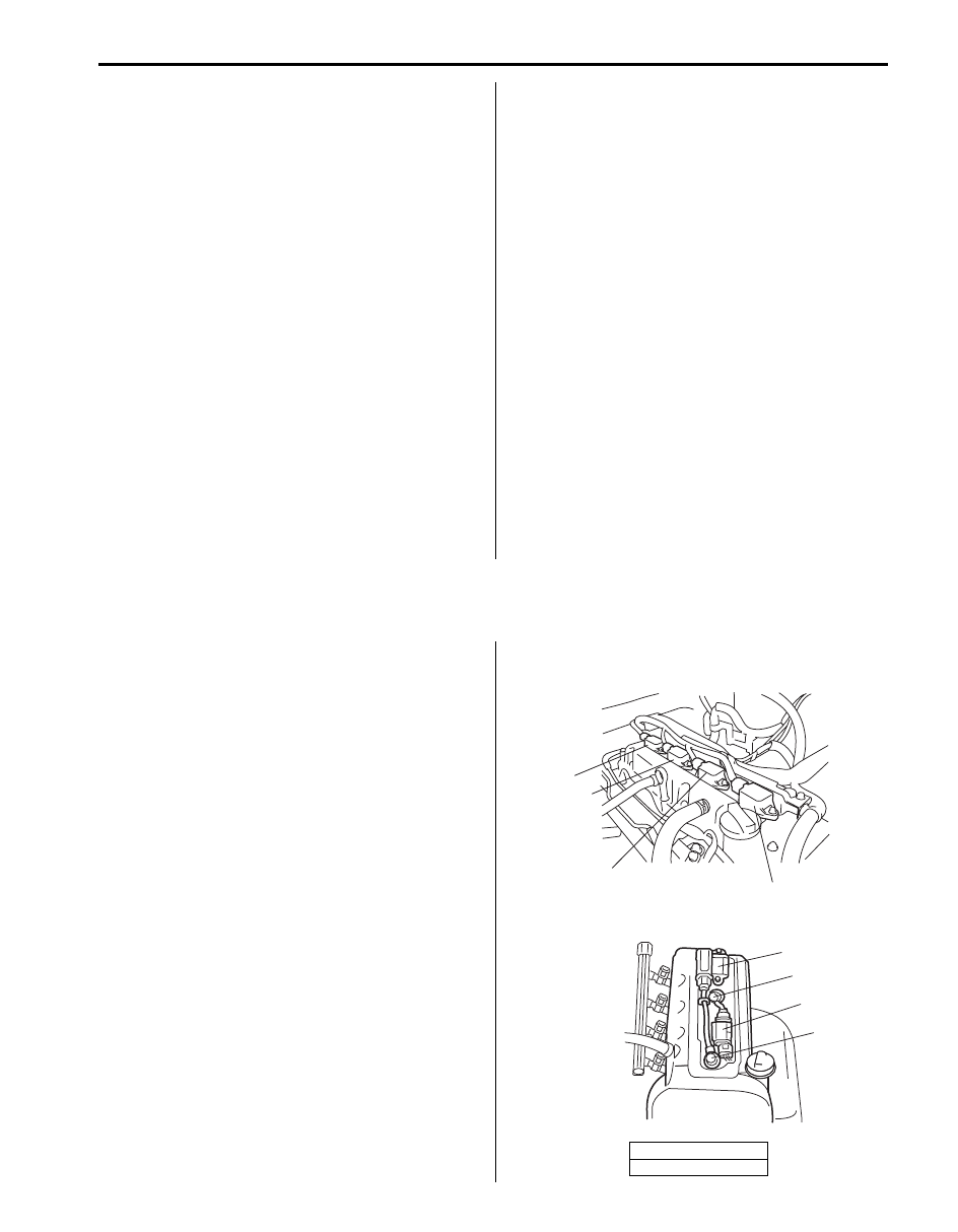
• The four cylinders of the engine are identified by
numbers; No.1 (1), No.2 (2), No.3 (3) and No.4 (4)
counted from crankshaft pulley side to flywheel side.
[A]: J20 engine
[B]: M16 engine
1
1
2
2
3
3
4
4
[A]
[B]
I5JB0A110001-02
1A-3 Engine General Information and Diagnosis:
Engine Diagnosis General Description
S5JB0A1101002
This vehicle is equipped with an engine and emission
control system which are under control of ECM.
The engine and emission control system in this vehicle
are controlled by ECM. ECM has an On-Board
Diagnostic system which detects a malfunction in this
system and abnormality of those parts that influence the
engine exhaust emission. When diagnosing engine
troubles, be sure to have full understanding of the outline
of “On-Board Diagnostic System Description” and each
item in “Precautions in Diagnosing Trouble” and execute
diagnosis according to “Engine and Emission Control
System Check”.
There is a close relationship between the engine
mechanical, engine cooling system, ignition system,
exhaust system, etc. and the engine and emission
control system in their structure and operation. In case of
an engine trouble, even when the malfunction indicator
lamp (MIL) doesn’t turn ON, it should be diagnosed
according to “Engine and Emission Control System
Check”.
On-Board Diagnostic System Description
S5JB0A1101003
Vehicle not Equipped with Diagnosis Connector
ECM in this vehicle has the following functions.
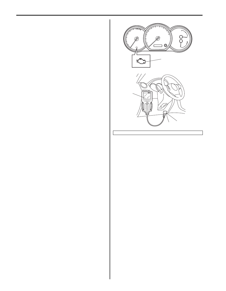
• When the ignition switch is turned ON with the engine
at a stop, malfunction indicator lamp (MIL) (1) turns
ON to check the circuit of the malfunction indicator
lamp (1).
• When ECM detects a malfunction which gives an
adverse effect to vehicle emission while the engine is
running, it makes the malfunction indicator lamp (1) in
the meter cluster of the instrument panel turn ON or
flash (flashing only when detecting a misfire which
can cause damage to the catalyst) and stores the
malfunction area in its memory.
(If it detects that continuously 3 driving cycles are
normal after detecting a malfunction, however, it
makes MIL (1) turn OFF although DTC stored in its
memory will remain.)
• As a condition for detecting a malfunction in some
areas in the system being monitored by ECM and
turning ON the malfunction indicator lamp (1) due to
that malfunction, 2 driving cycle detection logic is
adopted to prevent erroneous detection.
• When a malfunction is detected, engine and driving
conditions then are stored in ECM memory as freeze
frame data. (For the details, refer to description on
“Freeze Frame Data (Vehicle Not Equipped with
Diagnosis Connector): ”.)
• It is possible to communicate by using not only
SUZUKI scan tool (2) but also OBD generic scan tool.
(Diagnostic information can be accessed by using a
scan tool.)
Vehicle Equipped with Diagnosis Connector
ECM diagnosis troubles which may occur in the area
including the following parts when the ignition switch is
ON and the engine is running, and indicates the result by
turning on or flashing malfunction indicator lamp (1).
• A/F sensor (if equipped)
• Heated oxygen sensor (if equipped)
• ECT sensor
• TP sensor
• MAF sensor
• IAT sensor
• MAP sensor
• CMP sensor
• CKP sensor
• Knock sensor
• Wheel speed sensor
• CPU (Central Processing Unit) of ECM
• APP sensor
• Oil control valve (for M16 engine)
• Radiator cooling fan relay
ECM and malfunction indicator lamp (1) operate as
follows.
• Malfunction indicator lamp (1) lights when the ignition
switch is turned ON (but the engine at stop) with the
diagnosis switch terminal ungrounded regardless of
the condition of Engine and Emission control system.
This is only to check the malfunction indicator lamp (1)
in the combination meter and its circuit.
3. DLC
1
2
3
I5JB0A110002-01
Engine General Information and Diagnosis: 1A-4
• If the above areas of Engine and Emission control
system is free from any trouble after the engine start
(while engine is running), malfunction indicator lamp
(1) turns OFF.
• When ECM detects a trouble which has occurred in
the above areas, it makes malfunction indicator lamp
(1) turn ON while the engine is running to warn the
driver of such occurrence of trouble and at the same
time it stores the trouble area in ECM back-up
memory. (The memory is kept as it is even if the
trouble was only temporary and disappeared
immediately. And it is not erased unless the power to
ECM is shut off for specified time or it is cleared by
SUZUKI scan tool (2).)
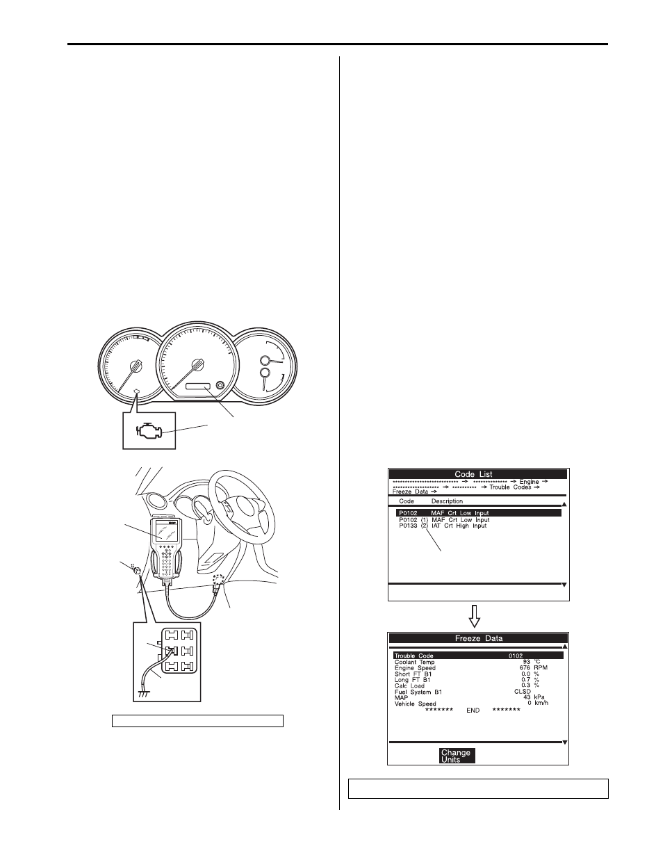
In addition, DTC can be read by not only using
SUZUKI scan tool but also displayed on odometer (5)
of the combination meter. (i.e. when diagnosis switch
terminal (3) is grounded with a service wire (4) and
ignition switch is turned ON.) For further detail of the
checking procedure, refer to “DTC Check”.
Warm-Up Cycle
A warm-up cycle means sufficient vehicle operation such
that the coolant temperature has risen by at least 22
°C
(40
°F) from engine starting and reaches a minimum
temperature of 70
°C (160 °F).
Driving Cycle
A “Driving Cycle” consists of engine startup and engine
shutoff.
2 Driving Cycle Detection Logic
The malfunction detected in the first driving cycle is
stored in ECM memory (in the form of pending DTC) but
the malfunction indicator lamp does not light at this time.
It lights up at the second detection of same malfunction
also in the next driving cycle.
Pending DTC
Pending DTC means a DTC detected and stored
temporarily at 1 driving cycle of the DTC which is
detected in the 2 driving cycle detection logic.
Freeze Frame Data (Vehicle Not Equipped with
Diagnosis Connector)
ECM stores the engine and driving conditions (in the
form of data as shown in the figure) at the moment of the
detection of a malfunction in its memory. This data is
called “Freeze frame data”.
Therefore, it is possible to know engine and driving
conditions (e.g., whether the engine was warm or not,
where the vehicle was running or stopped, where air/fuel
mixture was lean or rich) when a malfunction was
detected by checking the freeze frame data. Also, ECM
has a function to store each freeze frame data for three
different malfunctions in the order as each malfunction is
detected. Utilizing this function, it is possible to know the
order of malfunctions that have been detected. Its use is
helpful when rechecking or diagnosing a trouble.
6. Diagnosis connector
1
5
6
2
3
4
I5JB0A110003-01
[A]: 1st or 2nd in parentheses here represents which position in the order
the malfunction is detected.
[A]
I3RB0A110002-01
Нет комментариевНе стесняйтесь поделиться с нами вашим ценным мнением.
Текст