Suzuki Grand Vitara JB416 / JB420. Manual — part 326

8B-100 Air Bag System:
Installation
1) Connect driver air bag (inflator) module connector
(1) to driver air bag (inflator) module (2) securely as
shown in figure.
a) Connect connector.
b) Lock connector with lock button (3).
2) Install driver air bag (inflator) module (1) to steering
wheel (2), taking care so that no part of wire harness
is caught between them.
3) Make sure that clearance between module (1) and
steering wheel (2) is uniform all the way.
4) Tighten left side bolt (3) of driver air bag (inflator)
module first and then right side bolt (4).
Tightening torque
Driver air bag (inflator) module mounting bolt
(a): 9 N·m (0.9 kgf-m, 6.5 lb-ft)
5) Install steering wheel side caps (5).
6) Enable air bag system. Refer to “Enabling Air Bag
7) Connect negative cable at battery.
Driver Air Bag (Inflator) Module Inspection
S5JB0A8206006
WARNING
!
Never disassemble air bag (inflator) module
or measure its resistance. Otherwise,
personal injury may result.
CAUTION
!
If air bag (inflator) module was dropped from
a height of 90 cm (3 ft) or more, it should be
replaced.
Check air bag (inflator) module visually and if any of the
following is found, replace it with a new one.
• Air bag being deployed
• Trim cover (pad surface) (1) being cracked
• Inflator case (2) being damaged or having been
exposed to strong impact (dropped)
• Bend or deformity of air bag (inflator) module bracket.
Passenger Air Bag (Inflator) Module Removal
and Installation
S5JB0A8206007
WARNING
!
• Never attempt to disassemble or repair the
passenger air bag (inflator) module. If any
abnormality is found, be sure to replace it
with new one as an assembly.
• Be sure to read “Precautions on Service
and Diagnosis of Air Bag System”,
“Precautions on Handling and Storage of
Air Bag System Components” and
“Precautions on Disposal of Air Bag and
Seat Belt Pretensioner” before starting to
work and observe every precaution during
work. Neglecting them may result in
personal injury or undeployment of the air
bag when necessary.
b)
a)
3
1
2
I5JB0A820077-01
4, (a)
5
5
3, (a)
1
2
I5JB0A820078-01
2
1
I5JB0A820079-01
Air Bag System: 8B-101
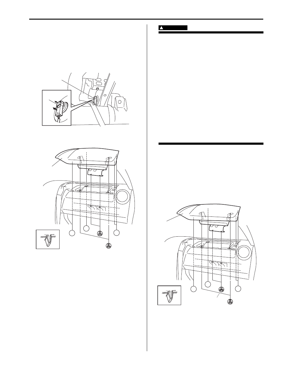
Removal
1) Disable air bag system. Refer to “Disabling Air Bag
2) Disconnect passenger air bag (inflator) module
connector (1) as shown in figure.
a) Unlock lock button (2).
b) With lock button unlocked, disconnect connector.
3) Remove passenger air bag (inflator) module (1) from
instrument panel as shown.
WARNING
!
• When carrying a live air bag (inflator)
module, make sure the bag opening is
pointed away from you.
Never carry air bag (inflator) module by
wires or connector on the side of the
module. In case of an accidental
deployment, the bag will then deploy with
minimal chance of injury.
• As the live passenger air bag (inflator)
module must be kept with its bag (trim
cover) facing up while being stored or left
standing. This is necessary so that a free
space is provided to allow the air bag to
expand in the unlikely event of accidental
deployment.
• Observe “Precautions on Handling and
Storage of Air Bag System Components”
for handling and storing it.
Otherwise, personal injury may result.
Installation
1) Install passenger air bag (inflator) module (1) to
instrument panel as shown.
2) Tighten passenger air bag (inflator) module attaching
bolts (2) to specified torque.
Tightening torque
Passenger air bag (inflator) module attaching
bolt (a): 23 N·m (2.3 kgf-m, 16.5 lb-ft)
2
1
a)
b)
I5JB0A820080-01
“A”
“A”
“A”
“A”
1
I5JB0A820081-01
“A”
“A”
“A”
“A”
2, (a)
1
I5JB0A820082-01

8B-102 Air Bag System:
3) Connect passenger air bag (inflator) module
connector (1) securely as shown in figure.
a) Connect connector.
b) Lock connector with lock button (2).
4) Enable air bag system. Refer to “Enabling Air Bag
Passenger Air Bag (Inflator) Module Inspection
S5JB0A8206008
WARNING
!
• Never measure resistance of passenger air
bag (inflator) module or disassemble it.
Otherwise personal injury may result.
• Never attempt to disassemble or repair the
passenger air bag (inflator) module. If any
abnormality is found, be sure to replace it
with new one as an assembly.
• Be sure to read “Precautions on Service
and Diagnosis of Air Bag System”,
“Precautions on Handling and Storage of
Air Bag System Components” and
“Precautions on Disposal of Air Bag and
Seat Belt Pretensioner” before starting to
work and observe every precaution during
work. Neglecting them may result in
personal injury or undeployment of the air
bag when necessary.
CAUTION
!
If air bag (Inflator) module was dropped from
a height of 90 cm (3 ft) or more, it should be
replaced.
Check air bag (inflator) module appearance visually for
the following symptoms and if any one of them is found,
replace with a new one.
• Air bag has deployed.
• Wire harness or connector is damaged.
• Air bag (inflator) module is damaged or a strong
impact was applied to it.
• Bend or deformity of air bag (inflator) module bracket.
Side-Air Bag (Inflator) Module Removal and
Installation
S5JB0A8206009
WARNING
!
• Never attempt to disassemble or repair the
side-air bag (inflator) module. If any
abnormality is found, be sure to replace it
with new one as an assembly.
• Be sure to read “Precautions on Service
and Diagnosis of Air Bag System”,
“Precautions on Handling and Storage of
Air Bag System Components” and
“Precautions on Disposal of Air Bag and
Seat Belt Pretensioner” before starting to
work and observe every precaution during
work. Neglecting them may result in
personal injury or undeployment of the air
bag when necessary.
Removal
1) Disable air bag system. Refer to “Disabling Air Bag
2) Roll up the seat surface of the seat back.
3) Remove sleeve lock nut (1) from seat back (2).
2
1
b)
a)
I5JB0A820083-01
I5JB0A820084-02
1
2
I4RS0A820067-01

Air Bag System: 8B-103
4) Remove side-air bag (inflator) module from seat
back.
5) Disconnect side-air bag (inflator) module connector
(1) as shown in figure.
a) Unlock lock button (2).
b) With lock button unlocked, disconnect connector.
WARNING
!
• When carrying a live air bag (inflator)
module, make sure the bag opening is
pointed away from you.
Never carry air bag (inflator) module by
wires or connector on the side of the
module. In case of an accidental
deployment, the bag will then deploy with
minimal chance of injury.
• As the live side-air bag (inflator) module
must be kept with its bag (trim cover)
facing up while being stored or left
standing. This is necessary so that a free
space is provided to allow the air bag to
expand in the unlikely event of accidental
deployment.
• Observe “Precautions on Handling and
Storage of Air Bag System Components”
for handling and storing it.
Otherwise, personal injury may result.
CAUTION
!
Do not damage the sleeve. Otherwise, the
side-air bag cannot be correctly installed to
seat back.
Installation
1) Confirm sleeve (1) is surely installed in side-air bag
(inflator) module.
2) Tighten sleeve lock nut (2) to specified torque.
Tightening torque
Sleeve lock nut (a): 2.5 N·m (0.25 kgf-m, 2.0 lb-
ft)
3) Install new clip to seat back.
4) Connect side-air bag (inflator) module connector (1)
securely as shown in figure.
a) Connect connector.
b) Lock connector with lock button (2).
5) Insert claw (1) of side-air bag (inflator) module on
installation hole (2).
6) Push side-air bag (inflator) module into clip (3) with
specified force.
Side-air bag (inflator) module installation force
Pushing force: 180 N
2
1
a)
b)
I4RS0A820068-01
1
2, (a)
I4RS0A820073-02
1
2
a)
b)
I4RS0A820070-01
1
2
3
I4RS0A820074-02
Нет комментариевНе стесняйтесь поделиться с нами вашим ценным мнением.
Текст