Suzuki Grand Vitara JB416 / JB420. Manual — part 69

1A-225 Engine General Information and Diagnosis:
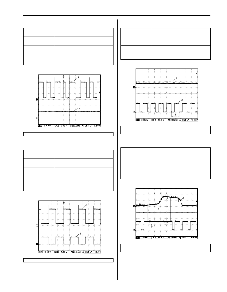
Reference waveform No.1
Fuel injector signal (1) with engine idling
Reference waveform No.2
No.1 fuel injector signal (2) with engine idling
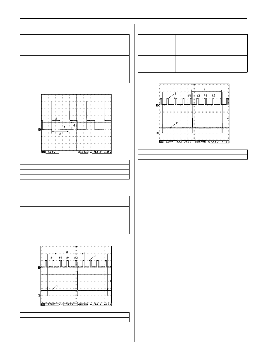
Reference waveform No.3
No.2 fuel injector signal (2) with engine idling
Reference waveform No.4
EGR valve signal
Measurement
terminal
CH1: “C37-2” to “C37-58”
Oscilloscope
setting
CH1: 20 V/DIV
TIME: 1 ms/DIV
Measurement
condition
• After warmed up to normal
operating temperature
• Engine at specified idle speed
2. Fuel injection pulse width: 2-4 msec.
3. 10 – 14 V
Measurement
terminal
CH1: “C37-52” to “C37-58”
CH2: “C37-1” to “C37-58”
Oscilloscope
setting
CH1: 5 V/DIV, CH2: 20 V/DIV
TIME: 40 ms/DIV
Measurement
condition
• After warmed up to normal
operating temperature
• Engine at specified idle speed
1. Cylinder reference signal (CMP reference signal)
3. 720
° crank angle
I5JB0A110074-01
I5JB0A110075-01
Measurement
terminal
CH1: “C37-52” to “C37-58”
CH2: “C37-2” to “C37-58”
Oscilloscope
setting
CH1: 5 V/DIV, CH2: 20 V/DIV
TIME: 40 ms/DIV
Measurement
condition
• After warmed up to normal
operating temperature
• Engine at specified idle speed
1. Cylinder reference signal (CMP reference signal)
3. 720
° crank angle
Measurement
terminal
CH1: “C37-5” to “C37-58”
CH2: “C37-6” to “C37-58”
CH3: “C37-3” to “C37-58”
CH4: “C37-4” to “C37-58”
Oscilloscope
setting
CH1: 20 V/DIV, CH2: 20 V/DIV
CH3: 20 V/DIV, CH4: 20 V/DIV
TIME: 40 ms/DIV
Measurement
condition
Engine at cranking
1. EGR valve stepper motor coil 1 signal
2. EGR valve stepper motor coil 2 signal
3. EGR valve stepper motor coil 3 signal
4. EGR valve stepper motor coil 4 signal
5. ON signal
6. OFF signal
I5JB0A110076-01
I4RS0B110053-01
Engine General Information and Diagnosis: 1A-226
Reference waveform No.5
Generator field coil monitor signal (1) at engine idling
Reference waveform No.6
Generator field coil monitor signal (1) at engine idling
Reference waveform No.7
Heated oxygen sensor-2 signal (1) with engine idling
Reference waveform No.8
Heated oxygen sensor-2 signal (1) with engine racing
Measurement
terminal
CH1: “C37-8” to “C37-58”
CH2: “C37-28” to “C37-58”
Oscilloscope
setting
CH1: 5 V/DIV, CH2: 5 V/DIV
TIME: 20 ms/DIV
Measurement
condition
• After warmed up to normal
operating temperature
• Engine at specified idle speed
• All accessory switch turned off
2. Generator output control signal
Measurement
terminal
CH1: “C37-8” to “C37-58”
CH2: “C37-28” to “C37-58”
Oscilloscope
setting
CH1: 5 V/DIV, CH2: 5 V/DIV
TIME: 20 ms/DIV
Measurement
condition
• After warmed up to normal
operating temperature
• Engine at specified idle speed
• For a few sec. from headlight
switch turned ON
2. Generator output control signal
I5JB0A110077-01
I5JB0A110078-01
Measurement
terminal
CH1: “C37-11” to “C37-57”
CH2: “C37-47” to “C37-58”
Oscilloscope
setting
CH1: 200 mV/DIV, CH2: 10 V/DIV
TIME: 200 ms/DIV
Measurement
condition
• After warmed up to normal
operating temperature
• Engine at specified idle speed
2. Heated oxygen sensor-2 heater signal
3. One duty cycle
Measurement
terminal
CH1: “C37-11” to “C37-57”
CH2: “C37-47” to “C37-58”
Oscilloscope
setting
CH1: 500 mV/DIV, CH2: 10 V/DIV
TIME: 200 ms/DIV
Measurement
condition
• After warmed up to normal
operating temperature
• Engine racing
2. Heated oxygen sensor-2 heater signal
3. Engine racing
I5JB0A110079-01
I5JB0A110080-03
1A-227 Engine General Information and Diagnosis:
Reference waveform No.9
EVAP canister purge valve signal
Reference waveform No.10
No.3 fuel injector signal (2) with engine idling
Reference waveform No.11
No.4 fuel injector signal (2) with engine idling
Measurement
terminal
CH1: “C37-13” to “C37-58”
Oscilloscope
setting
CH1: 10 V/DIV
TIME: 40 ms/DIV
Measurement
condition
• After warmed up to normal
operating temperature
• Set EVAP canister purge valve at
52% by using “Misc Test” of scan
tool
1. ON signal
2. OFF signal
3. One duty cycle
4. 10 – 14 V
Measurement
terminal
CH1: “C37-52” to “C37-58”
CH2: “C37-16” to “C37-58”
Oscilloscope
setting
CH1: 5 V/DIV, CH2: 20 V/DIV
TIME: 40 ms/DIV
Measurement
condition
• After warmed up to normal
operating temperature
• Engine at specified idle speed
1. Cylinder reference signal (CMP reference signal)
3. 720
° crank angle
I4RS0B110067-01
I5JB0A110081-01
Measurement
terminal
CH1: “C37-52” to “C37-58”
CH2: “C37-17” to “C37-58”
Oscilloscope
setting
CH1: 5 V/DIV, CH2: 20 V/DIV
TIME: 40 ms/DIV
Measurement
condition
• After warmed up to normal
operating temperature
• Engine at specified idle speed
1. Cylinder reference signal (CMP reference signal)
3. 720
° crank angle
I5JB0A110082-01
Engine General Information and Diagnosis: 1A-228
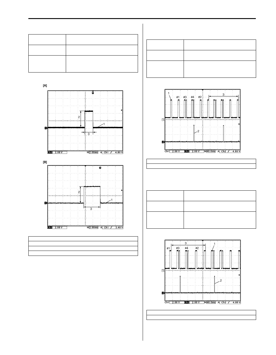
Reference waveform No.12
Ignition coil signal (1) with engine idling
Reference waveform No.13
Ignition coil No.4 signal (2) with engine idling (for J20
engine)
Reference waveform No.14
Ignition coil No.3 signal (2) with engine idling (for J20
engine)
Measurement
terminal
CH1: “C37-20” to “C37-58”
Oscilloscope
setting
CH1: 2 V/DIV
TIME: 2 ms/DIV
Measurement
condition
• After warmed up to normal
operating temperature
• Engine at specified idle speed
[A]: For J20 engine
[B]: For M16 engine
1. 4 – 6 V
3. Ignition coil pulse width
I5JB0A110083-02
Measurement
terminal
CH1: “C37-52” to “C37-58”
CH2: “C37-18” to “C37-58”
Oscilloscope
setting
CH1: 2 V/DIV, CH2: 2 V/DIV
TIME: 40 ms/DIV
Measurement
condition
• After warmed up to normal
operating temperature
• Engine at specified idle speed
1. Cylinder reference signal (CMP reference signal)
3. 720
° crank angle
Measurement
terminal
CH1: “C37-52” to “C37-58”
CH2: “C37-19” to “C37-58”
Oscilloscope
setting
CH1: 2 V/DIV, CH2: 2 V/DIV
TIME: 40 ms/DIV
Measurement
condition
• After warmed up to normal
operating temperature
• Engine at specified idle speed
1. Cylinder reference signal (CMP reference signal)
3. 720
° crank angle
I5JB0A110084-01
I5JB0A110085-01
Нет комментариевНе стесняйтесь поделиться с нами вашим ценным мнением.
Текст