BMW 3 (E46). Manual — part 236

600-1
General
A brief description of the principal parts
of the electrical system is presented
here. Also covered here are basic
electrical system troubleshooting tips.
See also
121 Battery, Alternator,
Starter
.
Electrical test equipment
Many electrical tests described in this
manual call for measuring voltage,
current, or resistance using a digital
multimeter. Digital meters are preferred
for precise measurements and for
electronics work because they are
generally more accurate than analog
meters. An analog meter (swing-
needle) may draw enough current to
damage sensitive electronic
components.
An LED test light is a safe, inexpensive
tool that can be used to perform many
simple electrical tests that would
otherwise require a digital multimeter.
The LED indicates when voltage is
present between any two test-points in
a circuit.
The integrated safety, comfort, security
and handling systems on E46 cars are
designed with self-diagnostic
capabilities. The quickest way to
diagnose many problems is to start out
with a scan tool read out of Diagnostic
Trouble Codes (DTCs). See
OBD
On Board Diagnostics
at rear of
manual.
Special Tools
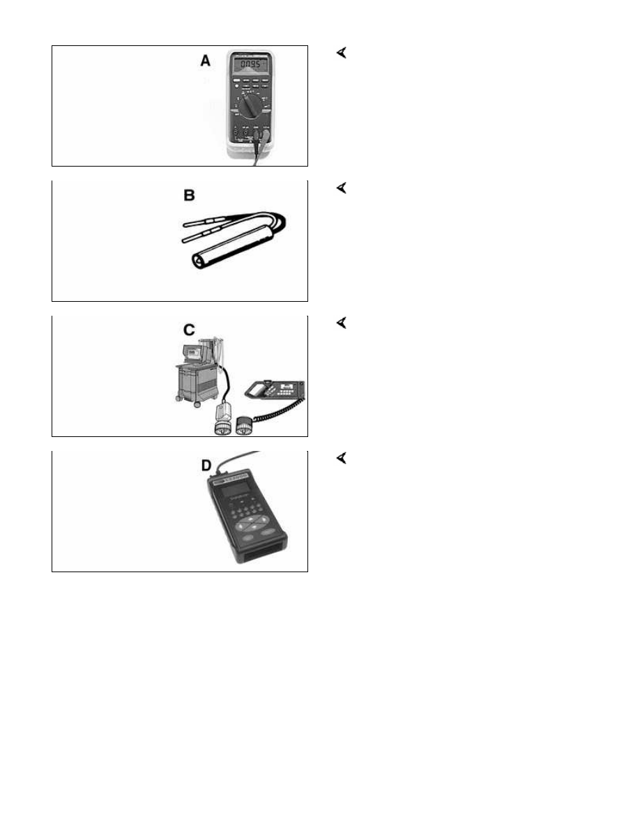
Automotive digital multimeter Fluke 87
LED tester with thin spade probes
Baum 1115 (Source: Baum Tools
Unlimited)
Scan tools BMW DIS/MoDiC
Aftermarket scan tool Baum CS2000
(Source: Baum Tools Unlimited)

600-2
E46 Electrical System
E46 cars are electrically complex. Many
vehicle systems and subsystems are
interconnected or integrated. In
addition, the requirements of second
generation On-Board Diagnostics (OBD
II) are such that there are now many
more circuits and wires in the vehicle
than ever before. The components
must exchange large volumes of data
with one another in order to perform
their various functions.
The use of dedicated data lines for
each link in the system has reached
the limits of its capabilities. On the one
hand, wiring harnesses now must be
so complex that they become
unmanageable. In addition, the finite
number of pins on conventional
connectors becomes a limiting factor in
electronic control module development.
The solution has been found in the use
of specialized, vehicle compatible serial
bus systems. The E46 bus system is
summarized in
Table a
.
Table a. E46 busses
Bus
Circuits covered
K-bus
Driver information
systems (instrument
cluster, Check Control,
on-board computer)
Central Body
Electronics (ZKE V)
General Module (GM
V)
Seat memory (SM)
Sunroof (SHD)
Rain sensor (AIC)
Telephone and sound
system
Headlight module
(LSZ)
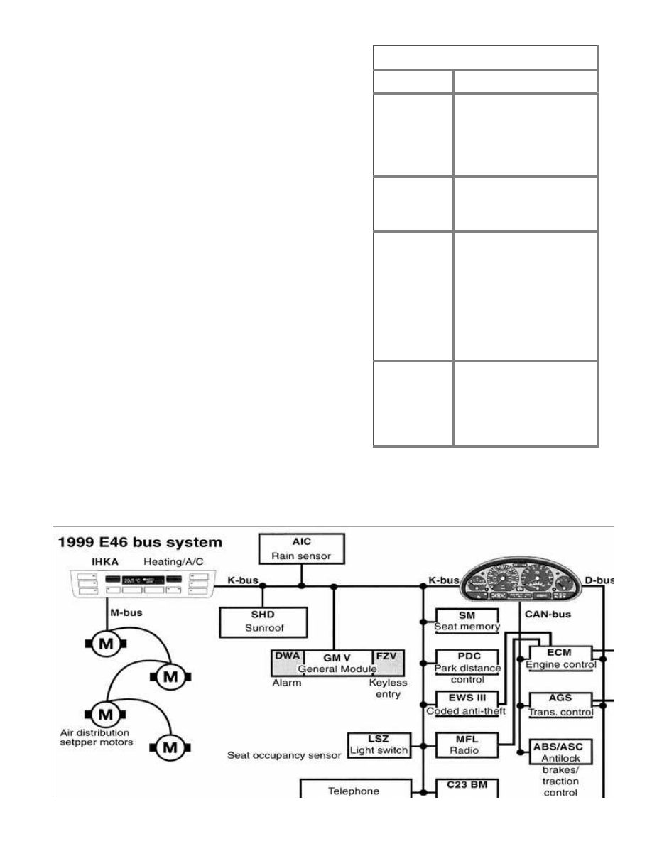
Table a. E46 busses
Bus
Circuits covered
Coded anti-theft (EWS
III) and anti-theft (DWA)
Remote entry (FZV)
Park distance control
(PDC)
M-bus
Heating and air
conditioning (IHKA)
components
CAN-bus
Engine management
system (DME)
Transmission control
(AGS)
Antilock brakes (ABS)
Traction control (ASC)
Dynamic stability
control (DSC)
D-bus
Data link connector
(DLC)
OBD II connector
Multiple restraint
system (MRS II)
1999 E46 bus system, diagram
Нет комментариевНе стесняйтесь поделиться с нами вашим ценным мнением.
Текст