BMW 3 (E46). Manual — part 82

quick tests.
Disconnecting the battery may
erase fault code(s) stored in
memory. Check for fault codes
prior to disconnecting the battery
cables.
Wait at least 40 seconds after
turning off the ignition before
removing the engine control
module (ECM) connector. If the
connector is removed before this
time, residual power in the system
relay may damage the control
module.
Cleanliness is essential when
working on an open fuel system.
Thoroughly clean fuel line
connections and surrounding
areas before loosening. Avoid
moving the car. Only install clean
parts.
Fuel system cleaners and other
chemical additives other than
those specifically recommended
by BMW may damage the catalytic
converter, the oxygen sensor or
other fuel supply components.

130-2
Electrical Checks and
Component Testing
Troubleshooting and fault diagnosis on
OBD II cars is best performed using an
electronic scan tool. However, it may
be necessary to perform basic tests of
the engine management main
components, fuel system or wiring.
CAUTION!
The tests in this section may set
fault codes (DTCs) in the ECM
and illuminate the MIL. After all
testing tests is completed,
access and clear DTC fault
memory using a BMW
compatible scan tool. See
OBD On Board Diagnostics
at
the back of this manual.
Only use a digital multimeter for
electrical tests.
Relay positions can vary. Be
sure to confirm relay position by
identifying the wiring in the
socket using the wiring
diagrams found at the rear of
this manual.
DME main relay, testing
The DME main relay is energized via
the engine control module (ECM) and
supplies battery positive (B+) power to
many of the engine management
components and subsystems. If this
relay is faulty, the engine will not start.
With ignition off, remove main relay
(arrow) in electronics box (E-box) at
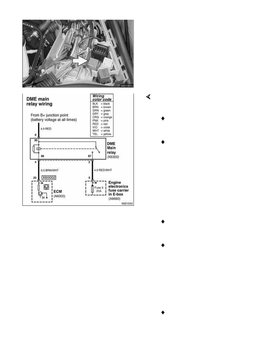
left rear of engine compartment.
Check for voltage at terminal 6 of main
relay socket (30- red wire).
If battery voltage is present
continue testing.
If battery voltage is not present,
check large red wire in relay
socket. See Electrical Wiring
Diagrams.
-
Reinstall relay and turn ignition
on. Gain access to underside of
relay socket and check for ground
at terminal 4 (85- brown/white
wire).
If ground is present continue
testing.
If ground is not present, signal
from ECM (connector X60002, pin
23) is missing. Check wire
between ECM and relay.
-
With ignition on and relay
installed, check for battery voltage
at terminal 2 (87- red/white wire).
If battery voltage is present, relay
has energized and is functioning
correctly.
If battery voltage is not present
and all earlier tests are OK, relay
is faulty and should be replaced.
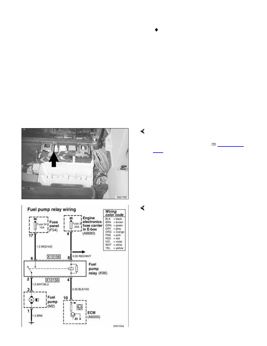
Fuel pump relay, testing
The ECM energizes the fuel pump
relay by providing the coil side of the
relay with ground. During starting, the
fuel pump runs as long as the ignition
switch is in the start position and
continues to run once the engine
starts. If the relay is faulty the fuel
pump will not run.
Fuel pump relay (arrow) is located
behind glove compartment. Remove
glove compartment. See
513 Interior
Trim
.
-
Remove fuel pump relay from
socket.
With ignition in START position, check
for battery voltage at relay connector
(X10156) terminals 6 and 8 (red/violet
andred/white wires).
CAUTION!
Ensure that manual transmission
vehicles are not in gear, and
automatic transmission vehicles are
in Park or Neutral prior to operating
ignition in START position.
-
With ignition in START position,
use digital multimeter to check for
ground at terminal 4 (black/violet
wire).
Note:
Нет комментариевНе стесняйтесь поделиться с нами вашим ценным мнением.
Текст