BMW 3 (E46). Manual — part 75
120-1
General
This repair group covers component
replacement information for the ignition
system.
When diagnosing engine management
problems, including on-board
diagnostics (OBD II) fault code
analysis, also refer to these repair
groups:
100 Engine–General
130 Fuel Injection
Electrical Wiring Diagrams at the
rear of this manual
OBD On Board Diagnostics
at
the rear of this manual
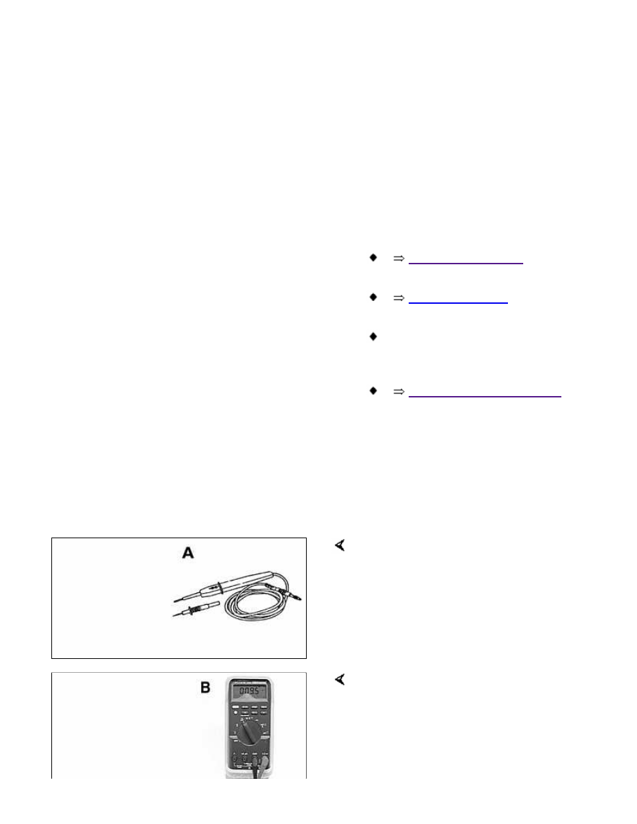
Special tools
Owing to the coil-per-cylinder
configuration, system diagnosis and
testing requires special test equipment.
LED test light Baum 1115 (Source:
Baum Tools Unlimited)
Automotive digital multimeter Fluke 87

Primary voltage test harness BMW 12 7
020
Secondary voltage test harness BMW
12 7 030
Ignition coil test adapters BMW 12 7
040
Engine management
BMW E46 engines use an advanced
engine management system known as
Digital Motor Electronics (DME). DME
incorporates on-board diagnostics, fuel
injection, ignition and other engine
control functions. DME variants are
listed in
Table a
.
Second generation On-Board
Diagnostics (OBD II) is incorporated
into the engine management systems
used on the cars covered by this
manual. Using a BMW-specific
electronic scan tool, it is possible to
access Diagnostic Trouble Codes
(DTCs) that pinpoint ignition and other
engine management problems.

Additional information about DTCs and
engine management system electronic
system diagnosis is provided in
OBD
On Board Diagnostics
at the rear of this
manual.
Table a. Engine management
systems
Year:
Engine
DME system
1999 - 2000:
M52 TU B25
M52 TU B28
Siemens MS 42.0
2001:
M54 B25
M54 B30
Siemens MS 43.0
Ignition system
All engines use a distributorless
ignition system with individual ignition
coils for each cylinder. There is no
distributor cap or ignition rotor.
Each coil can be controlled by the
Engine Control Module (ECM) on a
cylinder-by-cylinder basis.
Note:
Schematic diagram of ignition coil
circuit is for MS 42.0 engine
management system. On MS 43.0
system, ignition coil terminal 3 receives
power from Fuse 1 (30 amp). See
Electrical Wiring Diagrams for specific
wiring information.
WARNING!
Do not touch or disconnect any
cables from the coils while the
engine is running or being
cranked by the starter.
The ignition system produces
high voltages that can be fatal.
Avoid contact with exposed
terminals. Use extreme caution
when working on a car with the
ignition switched on or the
engine running.
Connect and disconnect the
DME system wiring and test
equipment leads only when the
ignition is OFF.
Before operating the starter
without starting the engine (for
example when making a
compression test) always
disable the ignition.
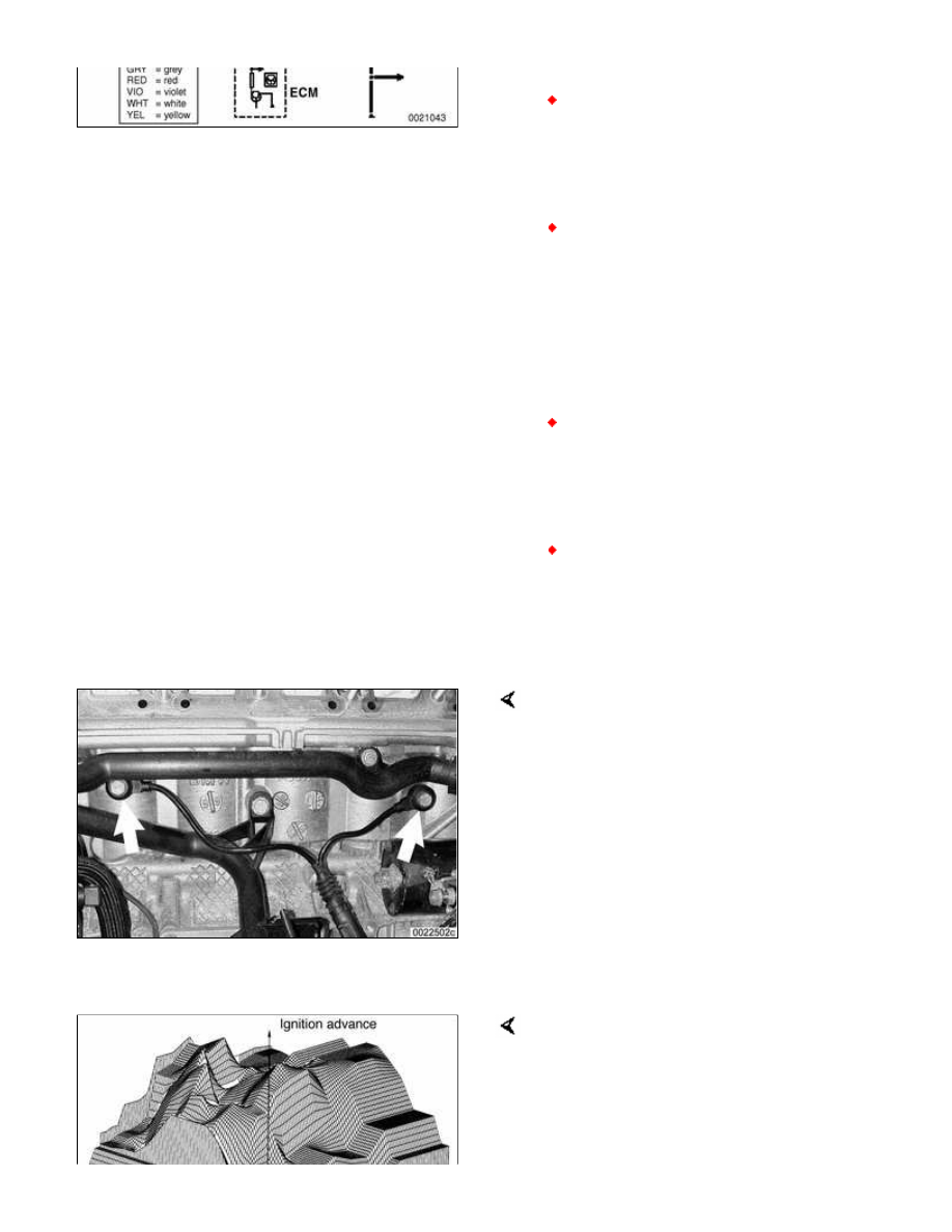
Knock sensors (arrows) monitor the
combustion chamber for engine-
damaging knock. Two sensors monitor
three cylinders each. If engine knock is
detected, the ignition point is retarded
by the ECM.
Note:
When knock is detected, ignition timing
will be retarded at the selective
cylinder(s) by 3° increments. If knock is
no longer detected, the timing will be
advanced in 1° increments.
Ignition timing is electronically mapped
and not adjustable. The ECM uses
engine load, engine speed, coolant
temperature, knock detection and
intake air temperature as the basic
inputs for timing control. A three
Нет комментариевНе стесняйтесь поделиться с нами вашим ценным мнением.
Текст