BMW 3 (E46). Manual — part 283

-
Poke a spray wand through IHKA
housing opening and spray
commercially available cleaning
agent on evaporator. Move wand
back and forth to cover evaporator
fins with liquid.
-
Allow 5 minutes for liquid to drip
through evaporator drain.
-
Start car and run heater and A/C at
maximum power for 5 minutes to
dry out evaporator.
Functional problems
IHKA self diagnostics monitors the inputs
and outputs of the system. If a fault is
detected, a Diagnostic Trouble Code
(DTC) is initially entered in RAM and
then in the EEPROM when the ignition is
switched off. A maximum of six DTCs
can be stored in the EEPROM when the
ignition is switched off. The E46 IHKA
module is connected to the Diagnostic
Link Connector (DLC) via the
K-bus/instrument cluster. Use DIS,
MoDiC or other suitable scan tool to
access DTCs.
When troubleshooting problems with the
E46 IHKA, it is important to note that
because the Car Memory/Key Memory
feature can change the functionality of
the system, a review of memory settings
should be performed prior to
condemning a component as faulty.
Substitute value operation
If an input potentiometer, sensor or
circuit fails or the signal from it is not
plausible, the control module ignores the
faulty signal and substitutes a

programmed substitute value. See
Table a
.
Table a. Substitute programmed
values for IHKA component inputs
Input
Working
range
Substitute
value
Heat
exchanger
sensor
5° to
124°C
(41° to
255°F)
55°C
(131°F)
Evaporator
sensor
-10° to
30°C (14°
to 86°F)
0°C (32°F)
Interior
temperature
sensor
10° to
40°C (50°
to 104°F)
20°C (68°F)
Exterior
temperature
K-bus
0°C (32°F)
Coolant
temperature
K -bus
100°C
(212°F)
Specified
temperature
16° to
32°C (61°
to 90°F)
22°C (72°F)
Note:
The substitute value for the evaporator
temperature sensor is below the A/C
compressor cycling temperature
(2°C/34°F). If the evaporator temperature
sensor signal is not plausible, the
substitute value will switch the A/C OFF.
Table b
lists resistance values and
fault limits for IHKA temperature sensors.
Table b. Temperature sensor
resistance values at 25°C (77°F)
Sensor
Resistance
Fault
limit
Heater core
9 k
± 2%
Temp >
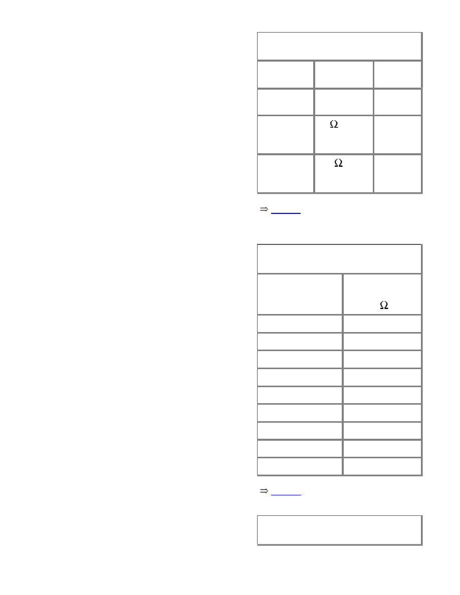
Table b. Temperature sensor
resistance values at 25°C (77°F)
Sensor
Resistance
Fault
limit
125°C
(257°F)
Evaporator
9 k
± 2%
Temp >
120°C
(248°F)
Interior
10 k
± 2%
Temp ≤
-46°C
(-51°F)
Table c
lists A/C evaporator
temperature-dependent resistance
values.
Table c. A/C evaporator temperature
sensor resistance values
Temperature
°C/°F
Resistance
range
k
-5/23
11.7 - 11.9
0/32
8.8 - 9.2
5/41
6.8 - 7.2
10/50
5.3 - 5.6
15/59
4.2 - 4.5
20/68
3.3 - 3.6
25/77
2.6 - 2.9
30/86
2.1 - 2.3
35/95
1.7 - 1.9
Table d
lists A/C expansion valve
pressure values.
Table d. Expansion valve pressure
values

Table d. Expansion valve pressure
values
Inlet pressure
14 bar (203 psi)
Outlet pressure
1.8 bar (26 psi)
Leak test with
detector pressure
1 - 2 bar
(14.5 - 29 psi)
A/C system warnings and
cautions
WARNING!
Always wear hand and eye
protection (gloves and goggles)
when working around the A/C
system. If refrigerant does come
in contact with your skin or eyes:
do not rub skin or eyes;
immediately flush skin or eyes
with cool water for 15 minutes;
rush to a doctor or hospital; do
not attempt to treat yourself.
Work in a well ventilated area.
Switch on exhaust/ventilation
systems when working on the
refrigerant system.
Do not expose any component of
the A/C system to high
temperatures (above 80C/176F) or
open flames. Excessive heat
causes a pressure increase which
could burst the system.
Keep refrigerant away from open
flames. Poisonous gas is
produced if it burns. Do not
smoke near refrigerant gases for
the same reason.
Нет комментариевНе стесняйтесь поделиться с нами вашим ценным мнением.
Текст