Hummer H1 (1992-1998). Manual — part 45
2-37. FUEL INJECTION NOZZLE REPAIR (Cont’d)
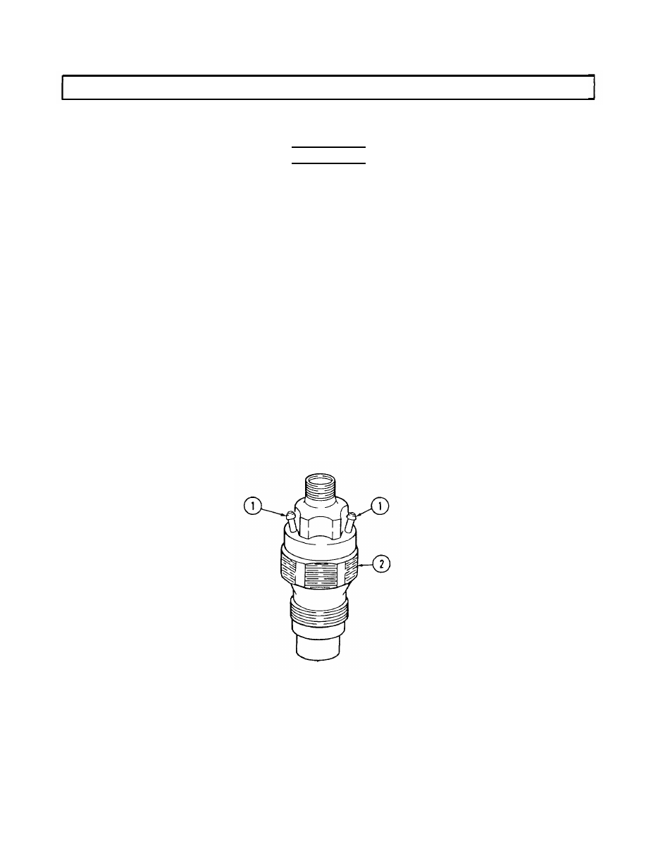
3. Leakage test.
(a) Open shutoff valve to pressure gauge one additional turn.
WARNING
Compressed air used for cleaning purposes will not exceed 30 psi
(207 kPa). Use only with effective chip guarding and personal
protective equipment (goggles/shield, gloves, etc.).
(b) Blow-dry end of nozzle (2).
NOTE
A pressure of 1,400 psi (9,653 kPa) must be maintained for
10 seconds while checking for nozzle leakage.
(c) Depress lever on tester until pressure gauge reads 1,400 psi (9,653 kPa) and observe tip
of nozzle (2). If a droplet forms and drops off the nozzle (2) in 10 seconds or less, replace
nozzle (2).
4. Chatter test.
(a) Close shutoff valve to pressure gauge.
(b) Depress lever on tester slowly, noting whether a chattering noise can be heard.
NOTE
Faster lever movement may cause nozzle to hiss or squeal rather
than chatter; this is acceptable.
(c) If no chatter is heard, increase speed of lever movement on tester until nozzle (2) chatters.
If no chatter is heard, replace nozzle (2).
2-143
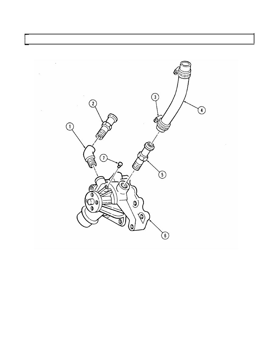
2-38. WATER PUMP REPAIR
This task covers:
a. Disassembly
c. Inspection
b. Cleaning
d. Assembly
INITIAL SETUP
Tools
Manual References
General mechanic’s tool kit:
automotive (Appendix E, Item 1)
Materials/Parts
Equipment Conndition
Engine disassembIed into subassemblies
Pipe sealing compound (Appendix B, Item 17)
Sealing compound (Appendix B, Item 18)
a. Disassembly
NOTE
Perform steps 1 through 3 if replacing water pump or damaged parts.
1. Loosen hose clamp (3) and remove bypass hose (4) from bypass hose adapter (5).
2. Remove 450 adapter (1) and heater hose nipple (2) from water pump (6).
3. Remove bypass hose adapter (5) from water pump (6).
b. Cleaning
Clean all components in accordance with para. 2-9.
c. Inspection
NOTE
For general inspection instructions, refer to para. 2-10.
1. Inspect heater hose nipple (2), 45° adapter (l), and bypass hose adapter (5) for thread damage.
Replace if threads are damaged.
2. Inspect water pump (6) for cracks and wear. Replace if cracked or worn.
3. Inspect threaded holes in water pump (6) for damage. Replace water pump (6) if threads are
damaged.
4. Inspect bypass hose (4) for damage. Replace if damaged.
5. Inspect water pump rivet (7) for damage or looseness. Replace if damaged or loose. Apply sealing
compound to replacement rivet prior to installation.
d. Assembly
1. Coat threads on 45° adapter (1) and heater hose nipple (2) with pipe sealing compound and install
in pump (6).
2. Coat threads on bypass hose adapter (5) with pipe sealing compound and install in water pump (6).
3. Install bypass hose (4) on bypass hose adapter (5) and secure with hose clamp (3).
NOTE
Perform step 4 if water pump was replaced.
4. Apply sealing compound to water pump rivet (7) and install in water pump (6).
2-144
2-38. WATER PUMP REPAIR (Cont’d)
2-145
2-39. WATER CROSSOVER REPAIR
This task covers:
a. Disassembly
c. Inspection
b. Cleaning
d. Assembly
INITIAL SETUP:
Tools
Manual References
General mechanic’s tool kit:
automotive (Appendix E, Item 1)
Equipment Condition
Materials/Parts
Engine disassembled
Water crossover gasket (Appendix D, Item 19)
Pipe sealing compound (Appendix B, Item 17)
into subassemblies
NOTE
In some cases, flanged head fasteners maybe present instead of
standard fasteners and washers. In all cases, washers should be
used when replacing a flanged head fastener with a standard
fastener.
a. Disassembly
1. Remove capscrew (6), stud (5), two washers (4), water outlet (7), thermostat (9), and gasket (8) from
water crossover (11). Discard gasket (8).
NOTE
Only perform steps 2 through 4 if replacing water crossover or
damaged parts.
2. Remove glow plug controller (1).
3. Remove temperature switch (3).
4. Remove de-airation nipple (2), bypass hose nipple (10), and heater hose nipple (12) from water
crossover (11).
Clean all components in accordance with para. 2-9.
NOTE
For general inspection instructions, refer to para. 2-10.
1. Inspect water crossover (11) and water outlet (7) for damage. Replace if damaged.
2. Inspect all threaded holes in water crossover (11) for thread damage. Replace if threads are
damaged.
3. Inspect heater hose nipple (12), de-airation nipple (2), and bypass hose nipple (10) for damage.
Replace if damaged.
4. Inspect glow plug controller (1), thermostat (9), and temperature switch (3) for damage. Replace
if damaged.
2-146
Нет комментариевНе стесняйтесь поделиться с нами вашим ценным мнением.
Текст