Hummer H1 (1992-1998). Manual — part 14
Change 1
2-45
2 - 1 6 . CYLINDER BLOCK REPAIR (Cont‘d)
NOT E
Occasionally during the honing operation, cylinder bore should be
thoroughly cleaned, and the piston-to-bore clearance checked for correct fit.
f.
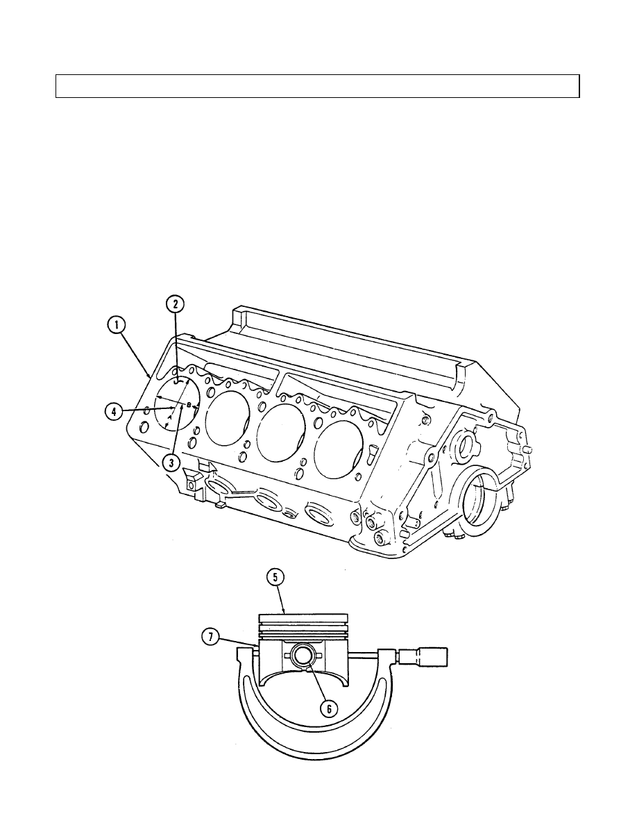
Using cylinder hone, refinish cylinder bore (2). Hone should be moved up and down at sufficient
speed to obtain very fine uniform surface finish marks, in a cross-hatch pattern of approximately
45° to 65° included angle. The finish marks should be clean, not sharp, and free from imbedded
particles and torn or folded material.
g. If a “Hi-Limit” piston or oversized piston (5) was fitted to a cylinder bore (2), permanently mark
the piston (5) for the cylinder bore (2) to which it has been fitted.
h. Repeat steps f. and g. for remaining cylinder bores.
i.
Thoroughly clean the cylinder block (1) with hot water and detergent. Scrub cylinder bores (2)
with a stiff brush and rinse thoroughly with hot water. The cylinder bores (2) should be coated
with OE/HDO and wiped with a clean, dry cloth.
2-46
Change 1
2 - 1 6 . CYLINDER BLOCK REPAIR (Cont‘d)
2.
Installation of cylinder sleeves.
CAUTION
Do not use cylinder sleeves to repair a cracked engine block.
NOTE
Cylinders that still show damage or wear after being honed to a
maximum oversize of 0.030 in. (0.762 mm) will require sleeves.
a. Identify cylinders that require sleeves.
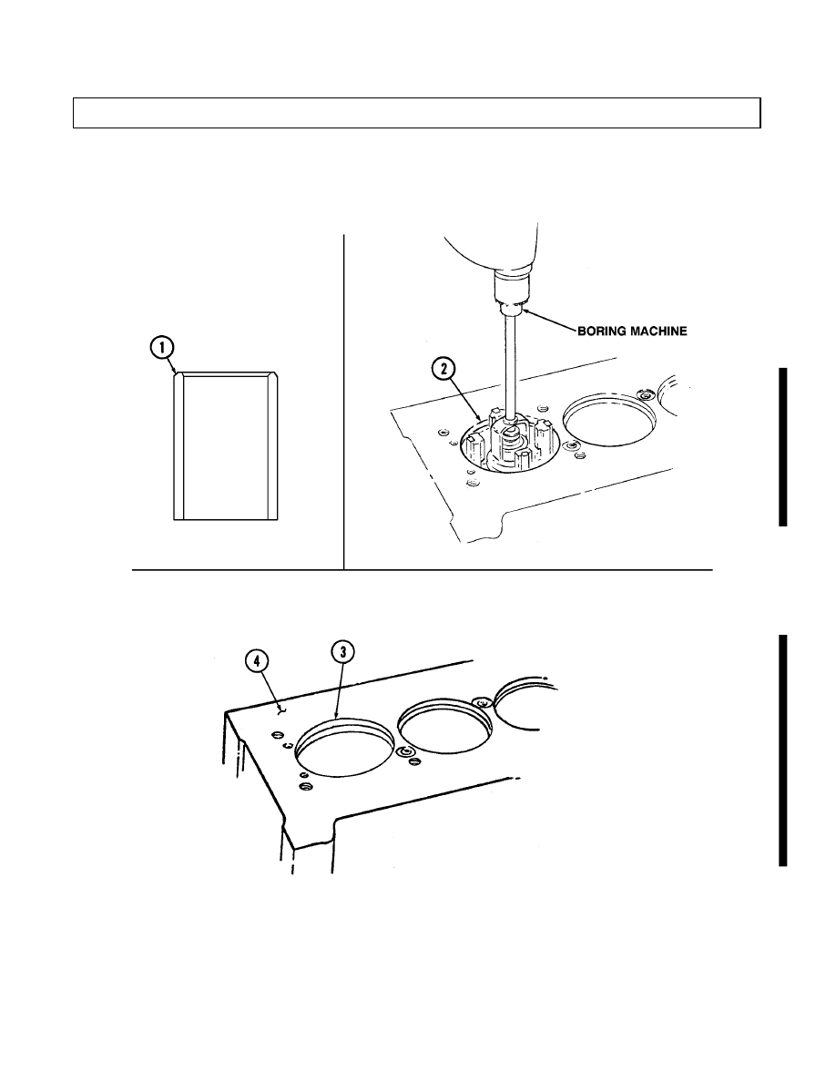
b. Using micrometer, measure outside diameter of cylinder sleeve (1).
NOTE
• Before using any type of boring bar, the top of the cylinder block
should be filed off to remove any dirt or burrs. This is very
important. If not checked, the boring bar may be tilted, which
would result in the rebored cylinder wall not being at right
angle to crankshaft.
• The cylinder must be bored to within 0.125 in. (3.18 mm) of the
rod relief in the bottom of the cylinder. Ensure the depth of the
bore does not exceed the length of the sleeve. Ensure to cut the
bottom of the bore square. This will provide a stop, or ledge, for
the sleeve to bottom out on.
c. Using cylinder boring machine, bore cylinder (2) to diameter of sleeve (1) less 0.002 to 0.003 in.
(0.051 to 0.076 mm) to create an interference fit between sleeve (1) and cylinder (2).
NOTE
Store the sleeve in a freezer at a temperature of 28 to 30°F (-2.2 to
-1.1°C) for several hours before installing it into the engine block.
d. Apply bead of high temperature sealing compound to top and bottom of cylinder (2) bore. Press
frozen sleeve (1) into cylinder (2) until it bottoms out on ledge at bottom of cylinder (2) bore.
e. Remove any excess sleeve material protruding above the head deck surface (4). Finish the
sleeve (1) flush with deck of block (3), taking care not to damage deck surface (4).
f.
Using cylinder boring machine, bore the sleeved cylinder (1) to appropriate piston size.
Change 1
2-47
2 - 1 6 . CYLINDER BLOCK REPAIR (Cont‘d)
2-16. CYLINDER BLOCK REPAIR (Cont’d)
3. Camshaft bearing replacement.
a.
b.
c.
d.
e.
f.
g.
h.
i.
j.
Remove
Remove
WARNING
Cylinder block must be supported during removal and installation
from engine stand. Failure to support cylinder block may cause
injury to personnel or damage to equipment.
NOTE
The following steps are to be performed only if camshaft bearings
are to be replaced.
cylinder block (2) from engine stand.
twenty capscrews (3) and five main bearing caps (4) from cylinder block (2).
Drive camshaft rear plug (1) from cylinder block (2). Discard plug (1).
Install adapter J 6098-11 in camshaft bearing number two (6).
Install pilot in number one camshaft bearing (5). Insert threaded rod through pilot and
into adapter.
thread
Hold threaded rod stationary and tighten long hex nut to remove camshaft bearing (6) from
cylinder block (2). When camshaft bearing (6) has been completely removed from cylinder
block (2), remove threaded rod, pilot, and adapter. Discard bearing (6).
Repeat steps d. through f. for number three camshaft bearing (7).
Repeat steps d. through f., working from rear of cylinder block (2), for number four camshaft
bearing (8).
Using driver handle and adapter J6098-11, remove number one camshaft bearing (5) from
cylinder block (2). Discard bearing (5).
Using driver handle and adapter J 6098-12, remove number five camshaft bearing (9) from
cylinder block (2). Discard bearing (9).
2-48
Нет комментариевНе стесняйтесь поделиться с нами вашим ценным мнением.
Текст