Hummer H1 (1992-1998). Manual — part 35
2-33. PRE-1990 (6.2L) FUEL INJECTION PUMP (DB2829-4523) CALIBRATION (Cont’d)
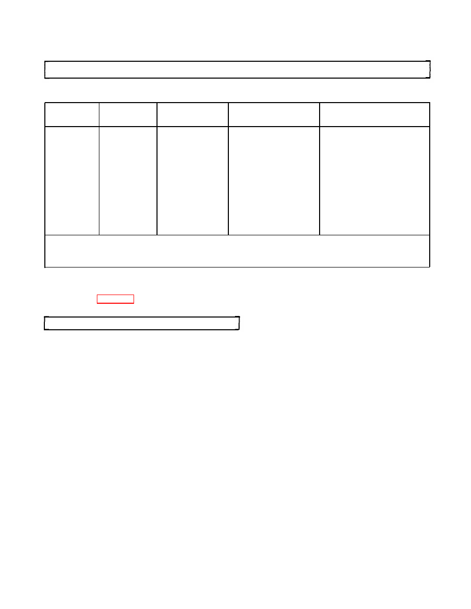
(b) Energize electric shutoff solenoid and check delivery against the chart below.
THROTTLE
MM
3
/
CAM MOVEMENT
RPM
POSITION
STROKE”
(DEGREES)
HOUSING PRESSURE
150
WOT
28 min.
400
WOT
47 min.
400
WOT***
4 max.
650
Low idle
10-18
1.5 min.
650
Low idle
2.75 min.
0-1 psi (0-6.9 kPa)**
1500
21.5-23.5
2.25-4.75
2000
WOT
51.0-55.0
0.5-2.5
3200
WOT
4.25-7.25
3200
Low idle
10.0 max.
3600
WOT
44.5 min.
3900
WOT
42.5 min.
4200
8 max.
* Maximum cylinder variation should be ± 6 mm
3
from the average flow of all cylinders.
** With housing pressure cold advance solenoid energized.
*** With electric shutoff solenoid de-energized.
10. Disconnect pump and mount in holding fixture.
11. Using air timing gage, check pump timing. Set to -0.75 to +1.25 degrees.
12. Refer to para. 2-7, Engine Troubleshooting, to diagnose any malfunctions encountered during
checkout.
d. Injection Pump Settings (Following Pump Repair)
1. Roller-to-roller dimension must be 1.981 ± 0.0005 in. (50.32 ± 0.013 mm). With oversize cam ring
installed, roller-to-roller dimension will be 1.987 ± 0.0005 in. (50.47 ± 0.013 mm). Maximum
eccentricity allowed is 0.008 in. (0.20 mm) TIR.
2. Linkage gap must be 0.130-0.175 in. (3.30-4.45 mm).
(a) Mount the pump horizontally in holding fixture and remove governor cover.
(b) Hold the throttle lever in the wide-open throttle (WOT) position. Rotate pump drive shaft
counterclockwise until a click is heard as the rounded contact points on the governor arm
engage the slots in the thrust sleeve. Continue to rotate the drive shaft until the gap between
the governor arm and pump housing is minimal.
(c) Using linkage gap tool, check the clearance limits between the rear of the shutoff shaft and
the vertical tab on the linkage hook.
(d) If adjustment is required, loosen governor linkage hook adjustment screw and extend the
linkage hook to its maximum open length (throttle lever must be in WOT).
(e) Insert the appropriate step of the linkage gap tool between the vertical hook tab and the
throttle shaft, with the step facing the shaft. The tool must be held vertically and parallel
to the linkage hook tab.
(f) With the linkage hook pin seated firmly in the governor arm slot and the governor arm in
the minimal gap position (step 2.(b)), shorten the linkage hook assembly until the face of the
vertical tab is flush against the tool. Tighten adjusting screw to 12-15 lb-in. (1 N•m).
(g) Recheck linkage gap and adjust if necessary.
2-128

2-33. PRE-1990 (6.2L) FUEL INJECTION PUMP (DB2829-4523) CALIBRATION (Cont’d)
3.
4.
5.
6.
7.
8.
9.
10.
11.
12.
13.
14.
15.
16.
17.
Set the throttle lever in correct low idle position prior to calibration using throttle lever gauge. The
low idle screw must beat 34 ± 2 degrees as measured between vertical centerline of throttle shaft
bushing bore and throttle connection stud.
Flush the pump with calibrating oil to remove metal chips and possible contamination.
Before mounting the pump on the test stand, check the drive shaft for freedom of rotation in the
housing. Pump should be mounted securely in the appropriate adapter, and the intermediate
coupling checked for freedom of movement.
Connect supply and return lines securely.
Install high pressure injection lines. Use copper gaskets or steel washers where required. Leave fuel
line connections at the pump and nozzles loose.
Apply 17.6 V to electric shutoff solenoid and operate pump at 2000 rpm (WOT) for 10 minutes to
bring to operating temperature and clear air from system.
Tighten all connections securely. Check connections for leaks while operating.
Set transfer pump pressure at 2000 rpm (WOT) for 70-76 psi (482.7-524 kPa); test stand boost
should be set at 5 ± 0.5 psi (34.5 ± 3.4 kPa).
Set return oil flow to 225-375 cc/minute at 2000 rpm (WOT).
Measure housing pressure:
(a) Check housing pressure at 650 rpm, with throttle shaft in low idle position, pressure should
be 8-12 psi (55-83 kPa).
(b) Energize housing pressure cold advance solenoid with 17.6 V, housing pressure should be
0-1 psi (0-6.9 kPa).
With governor cover removed and throttle shaft in low idle position, set min-max governor assembly
for 14.0 ± 2 mm
3
/stroke at 650 rpm (fuel reading with cover installed).
Check electric shutoff solenoid for pull-in with 17.6 V maximum with throttle lever in low idle
position at 400 rpm.
Transfer pump lift should be 18 in. Hg (60.8 kPa) at 400 rpm.
Mechanical/Light Load Advance Setting
(a) Check housing pressure at 650 rpm, with throttle shaft in low idle position, pressure should
be 8-12 psi (55-83 kPa).
(b) With throttle in a WOT position, rotate face cam to its maximum lift position in contact with
the cam roller.
(c) At 2000 rpm, adjust trimmer screw for 1.5 degrees cam advance.
(d) Set throttle for 22.5 ± 1 mm
3
/stroke at 1500 rpm and rotate face cam to obtain 3.5 degrees
cam advance.
(e) Tighten face cam screw to 28-32 lb-in. (3-4 N•m) and check face cam retention.
(1) Put 0.005-in. (0.127 mm) feeler gauge between throttle shaft mylar washer and housing
(2) Put throttle shaft in idle position. Squeeze throttle shaft and face cam tightly toward each
other and rotate face cam as lower roller rests approximately in middle at low idle step.
Tighten screw to 30 lb-in. (3 N•m) with torx drive and remove feeler gauge.
Set total throttle travel, With throttle in low idle position, align zero degree mark on protractor
with center of rib on rocker lever. Move throttle to WOT and adjust maximum travel screw to
80-84 degrees.
2-33. PRE-1990 (6.2L) FUEL INJECTION PUMP (DB2829-4523) CALIBRATION (Cont’d)
NOTE
Any changes to pump or settings after this point will require
retesting of pump, starting with step 16.
18. Fuel delivery measurement:
(a) In order to minimize variations between readings due to residual oil in the graduates, the
following timed cycle should be used:
(1) Draw
(2) Settle 30 seconds
(3) Drain 30 seconds
(4) Draw
(5) Settle 30 seconds
(6) Read graduates
(7) Repeat cycle and average readings
(b) Check points:
(1) At 1500 rpm (WOT) de-energize electric shutoff solenoid. Delivery should be 4 mm
3
/stroke
maximum.
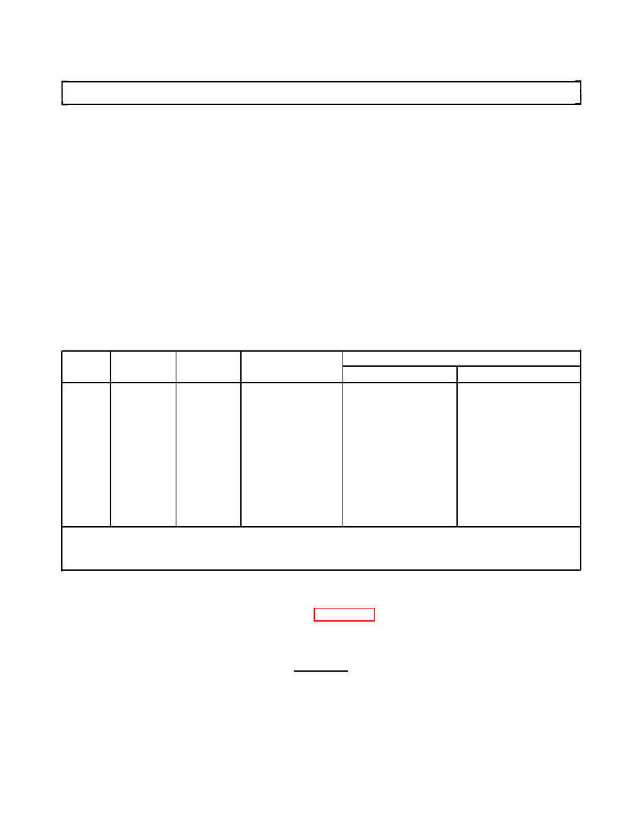
(2) Re-energize electric shutoff solenoid and check delivery against the chart below.
THROTTLE
MM
3
/
CAM MOVEMENT
PRESSURE
RPM
POSITION
STROKE*
(DEGREES)
TRANSFER PUMP
HOUSING
150
WOT
28 min.
12 psi (83 kPa) min.
400
WOT
47 min.
400
WOT***
4 max.
650
Lo
W
idle
12-16
1.5 min.
650
Low idle
2.75 min.
0-1 psi (0-7 kPa)**
1500
21.5-23.5
2.5-4.5
8-12 psi (55-83 kPa)
2000
WOT
51.0-55.0
0.5-2.5
8-12 psi (55-83 kPa)
3200
WOT
4.25-6.75
8-12 psi (55-83 kPa)
3200
Low idle
10.0 max.
8-12 psi (55-83 kPa)
3600
WOT
46 min.
3900
WOT
44 min.
4200
WOT
8 max.
135 psi (931 kPa) max.
* Maximum cylinder variation should be ± 6 mm
3
from the average flow of all cylinders.
** With housing pressure cold advance solenoid energized.
*** With electric shutoff solenoid de-energized.
19.
Disconnect pump and mount in holding fixture.
20. Using air timing gauge, check pump timing. Set to +0.25 degree* 0.50 degree.
21. Tighten all fasteners to specifications, refer to para. 2-32d.
22. Apply sealing compound as follows:
(a) Apply one drop at interface of maximum travel screw and locknut.
CAUTION
Do not allow sealing compound to enter gap between face cam and
housing. Binding of the throttle shaft may result.
(b) Apply one drop to threaded end of face cam screw where it protrudes from face cam.
(c) Apply one drop to interface of servo advance adjusting screw and rocker lever, making sure
sealing compound does not enter hex recess of screw.
2-130

2-34. 1990 (6.2L) FUEL INJECTION PUMP (DB2829-4879) CALIBRATION
This task covers:
a. Test Bench Requirements
c. Injection Pump Check (Prior to Service)
b. Injection Pump Information
d. Injection Pump Settings (Following Pump Repair)
INITIAL SETUP:
Tools
Manual References
General mechanic’s tool kit:
automotive (Appendix E, Item 1)
Test Equipment
Special Tools
Digital tachometer
Roller-to-roller setting tool
Voltage source (variable)
(Appendix E, Item 45)
Pressure gauge (0-160 psi, 1 psi increments)
Linkage gap tool (Appendix E, Item 49)
Pressure gauge (0-30 psi)
Automatic advance indicator
(Appendix E, Item 50)
Vacuum gauge (0-30-in. Hg)
Flowmeter with three-way valve
Throttle lever gauge (Appendix E, Item 51)
Temperature gauge (0°-250¯F)
Protractor (Appendix E, Item 52)
Zero-backlash coupling device
Air timing gauge (Appendix E, Item 53)
Calibrating nozzles and lines
Holding fixture (Appendix E, Item 46)
Orifice 13211
Torx drive (Appendix E, Item 42)
Calibration stand
Materials/Parts
Calibrating fluid (Appendix B, Item 4)
Sealing compound (Appendix B, Item 19)
NOTE
The following calibration procedure applies to 1990 6.2L and above
fuel injection pumps. Refer to para. 2-33 for calibration on
pre-1990 6.2L pumps and para 2-35 for 6.5L pumps.
a. Test Bench Requirements
The fuel injection pump requires a test bench capable of at least 2250 rpm shaft speed. The test
bench must be equipped with the following items:
(a) A zero-backlash coupling device.
(b) A digital tachometer.
(c) A variable voltage source.
(d) Test gauges:
(1)
(2)
(3)
(4)
(5)
0-160 psi (0-1103 kPa) pressure gauge calibrated in 1 psi increments to measure transfer
pump pressure. This gauge should be located as close as possible to the pump, with an
in-line shutoff valve located at the pump.
0-30 psi (0-206.9 kPa) pressure gauge to measure housing pressure.
0-30 in. Hg (0-101.3 kPa) vacuum gauge to measure transfer pump lift. This gauge should be in
the supply line to the pump, with a shutoff valve between the gauge and the oil source.
A flowmeter for measuring return oil should be used with a three-way valve to permit the
flowmeter to be in use only during the return oil check.
0°-250°F (-17.8°-121.1°C) temperature gauge, located at the pump inlet, to monitor inlet
temperature.
2-131
Нет комментариевНе стесняйтесь поделиться с нами вашим ценным мнением.
Текст