Hummer H1 (1992-1998). Manual — part 28
2-32. FUEL INJECTION PUMP REPAIR (Cont’d)
11. Inspect throttle shaft bushings (1) for damage. If damaged, perform steps 12 through 20 using
throttle and shutoff shaft bushing installation kit. If not, go to step 21.
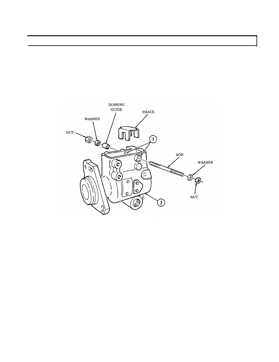
12. Install brace into housing (2) to prevent distortion of housing (2) during bushing (1) removal.
13. Install rod through bushings (1).
14. Install bushing guide, two washers, and nuts.
15. Tighten nuts until bushing (1) is removed from housing (2). Remove tools and discard bushing (1).
2-100
2-32. FUEL INJECTION PUMP REPAIR (Cont’d)
16.
17.
18.
19.
20.
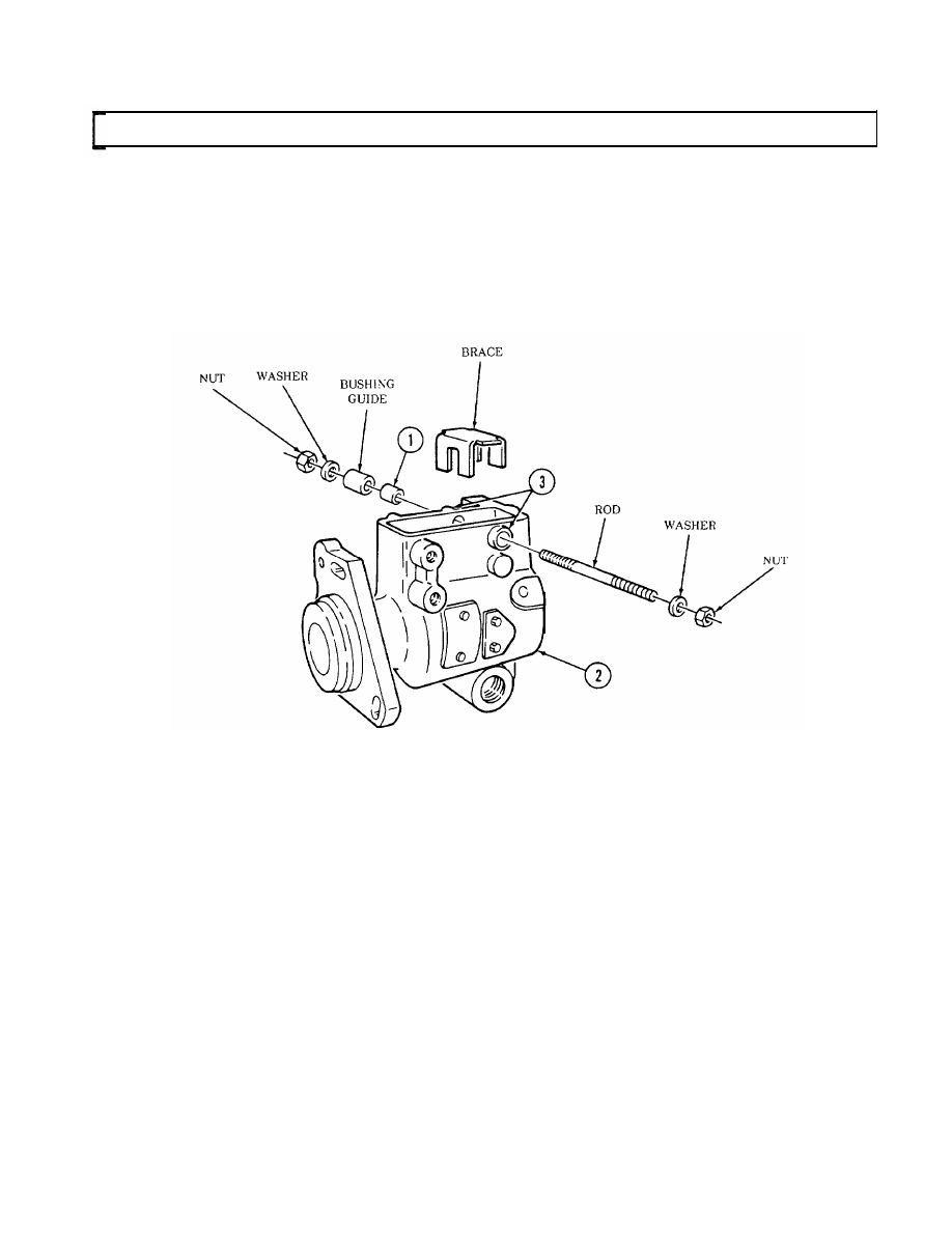
Install brace and rod into housing (2).
Apply sealing compound to outside diameter of bushing (1).
Install bushing (1), bushing guide, two washers, and nuts on rod.
Tighten nuts
housing (2).
Repeat steps
until bushing (1) is past flush with bushing boss (3) on housing (2). Remove tools from
12 through 19 for opposite bushing, if required.
2-101
2-32. FUEL INJECTION PUMP REPAIR (Cont’d)
2-102
Change 2
21.
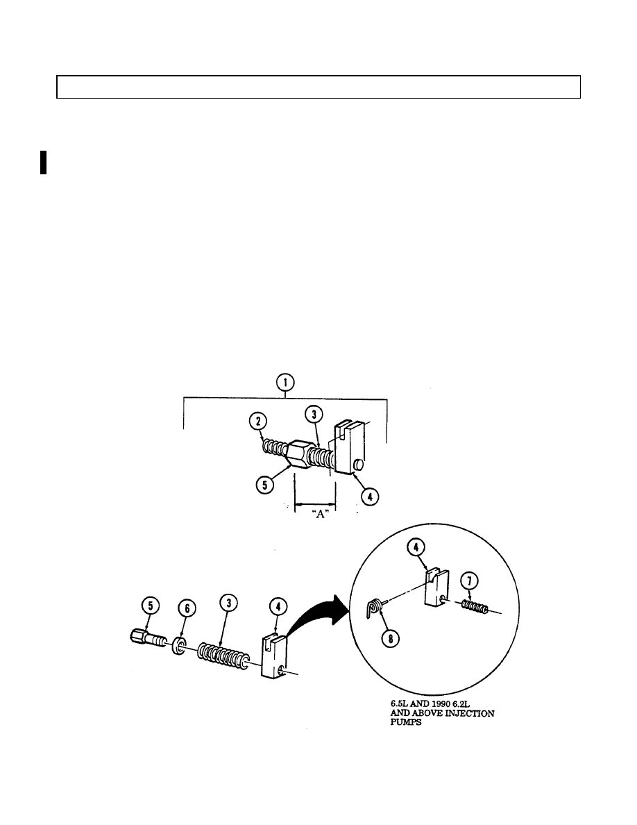
Inspect idle spring (2) on min-max governor (1) for corrosion or damage. Replace if corroded or
damaged.
N
NO
OT
TE
E
Perform steps 22 and 23 for 6.5L engines and 6.2L engines 1990
and above.
22.
Inspect inner governor spring (7) for corrosion or damage. Replace if corroded or damaged.
23.
Inspect governor thrust spring (8) for corrosion or damage. Replace if corroded or damaged.
24.
Inspect min-max spring (3) for corrosion or damage. If corroded or damaged, perform steps 25
through 29. If not, go to step 30.
25.
Remove idle spring (2) from pushrod (5).
26.
Measure distance “A” from throttle block (4) to end of pushrod (5) for assembly.
27.
Put throttle block (4) in vise and remove pushrod (5), spring (3), and washer (6). Discard spring (3).
28.
Install washer (6) and spring (3) on pushrod (5) and install into throttle block (4).
29.
Tighten pushrod (5) until measurement taken in step 26 is obtained.

2-32. FUEL INJECTION PUMP REPAIR (Cont’d)
30. Inspect regulatar (10) for damage. Replace if damaged.
NOTE
When removing roll pin, note which hole from where pin is
removed, It is marked “C” or “CC”.
31. Inspect roll pin (9) in regulator (10) for damage. Replace if damaged.
32. Inspect arm spring (11) for damage. Replace if damaged.
CAUTION
Metering valves are available in standard and oversize. If
replacing metering valve, check for number “SB-336” on top of
hydraulic head. If number is present, oversize metering valve
must be used or injection pump may malfunction.
33. Inspect metering valve (12) and arm (13) for damage. If damaged, perform steps 34 and 35. If not,
go to step 36.
34. Place valve (12) in holding fixture hole and remove arm (13) from valve (12).
35. Install arm (13) on valve (12).
Нет комментариевНе стесняйтесь поделиться с нами вашим ценным мнением.
Текст