Hummer H1 (1992-1998). Manual — part 9

Change 1
2-25
2 - 1 5 . ENGINE DISASSEMBLY INTO SUBASSEMBLIES (Cont’d)
p. Water Pump and Adapter Plate
1.
Remove two nuts (6), washers (7), and oil fill tube (8) from adapter plate (9).
2.
Remove two studs (10), (14), and (17), four capscrews (18), washers (11), two capscrews (15),
capscrew (16), water pump (13), and adapter plate (9) from timing gear cover (12).
.
WARNING
.
Gaskets installed on some 6.2L engines assembled prior to 1991
may contain asbestos. Gaskets should be removed with a scraper
or putty knife and then be disposed of IAW current directives.
Inhalation of asbestos fibers can cause respiratory ailments.
3.
Remove seven capscrews (20) from water pump (13) and separate water pump (13) and gasket (19)
from adapter plate (9). Discard gasket (19).
2-26
Change 1
2 - 1 5 . ENGINE DISASSEMBLY INTO SUBASSEMBLIES (Cont’d)
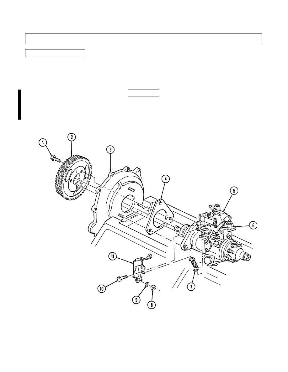
q. Fuel Injection Pump
1.
Remove three capscrews (1) and pump driven gear (2) from fuel injection pump (5).
2.
Remove idle return spring (7) from throttle lever (6).
3.
Remove three nuts (8) and washers (9) from fuel injection pump (5) and timing gear cover (3).
4.
Remove two capscrews (10) and accelerator cable bracket (11) from fuel injection pump (5).
.
WARNING
.
Gaskets installed on some 6.2L engines assembled prior to 1991
may contain asbestos. Gaskets should be removed with a scraper
or putty knife and then be disposed of IAW current directives.
Inhalation of asbestos fibers can cause respiratory ailments.
5.
Remove the fuel injection pump (5) and gasket (4) from cover (3). Discard gasket (4).
2-15. ENGINE DISASSEMBLY INTO SUBASSEMBLIES (Cont’d)
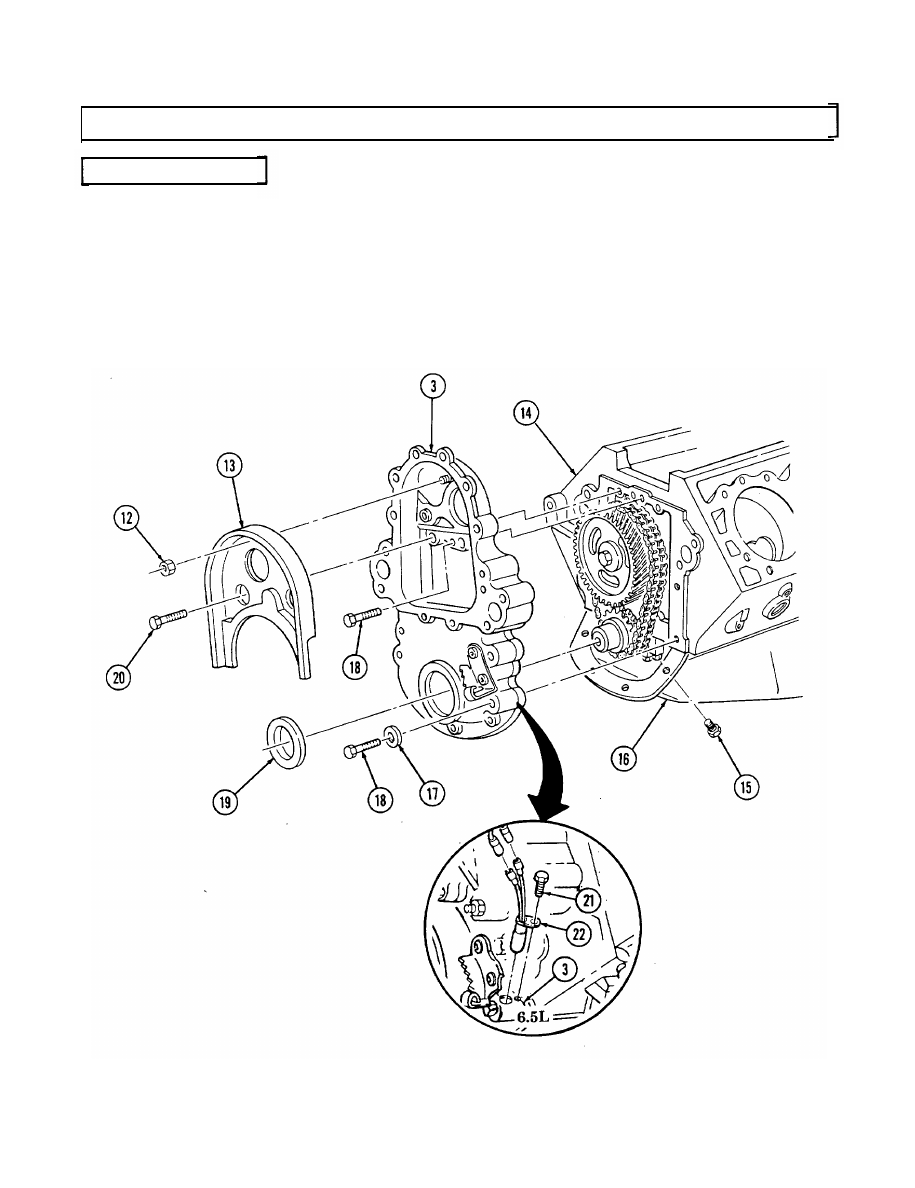
r. Timing Gear Cover
NOTE
Perform step 1 for 6.5L engines.
1. Remove capscrew (21) and rpm sensor (22) from timing gear cover (3).
2. Remove two capscrews (20), nut (12), and baffle (13) from timing gear cover (3).
3. Remove four capscrews (15) from oil pan (16) and timing gear cover (3).
4. Remove five capscrews (18), four washers (17), and timing gear cover (3) from cylinder block (14).
5. Remove front cover seal (19) from timing gear cover (3). Discard seal (19).
2-27
2-15. ENGINE DISASSEMBLY INTO SUBASSEMBLIES (Cont’d)
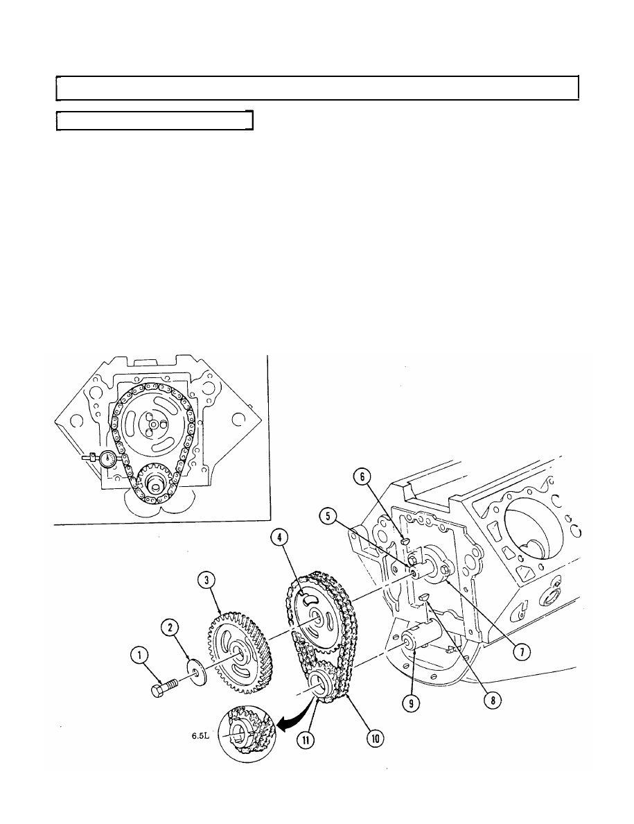
s. Timing Chain and Drive Sprockets
NOTE
When measuring timing chain deflection, slack should be removed
from one side before measurement is taken on opposite side.
1. Using dial indicator, check timing chain (10) deflection midway between camshaft sprocket (4) and
crankshaft sprocket (11). Total deflection must not exceed 0.810-in. (20.6 mm). If deflection exceeds
specification, timing chain (10) must be replaced.
2. Using dial indicator, check camshaft end play. Camshaft end play must not be more than 0.012-in.
(0.3 mm). If end play exceeds specification, camshaft sprocket (4), thrust plate (7), and spacer must
be inspected for wear after removal.
3. Remove capscrew (1), washer (2), and pump drive gear (3) from camshaft (5).
4. Remove crankshaft sprocket (11), camshaft sprocket (4), and timing chain (10) as an assembly.
NOTE
Cover oil pan opening to prevent woodruff key from falling into oil pan.
5. Remove woodruff key (8) from crankshaft (9) and woodruff key (6) from camshaft (5). Discard
woodruff keys (8) and (6).
2-28
Нет комментариевНе стесняйтесь поделиться с нами вашим ценным мнением.
Текст