Hummer H1 (2002+). Manual — part 76

___________________________________________
Transmission/Transfer Case 5-103
®
05745159
14
Replace the 2-3 shift solenoid valve.
Is replacement complete?
—
Go to step 15
—
15
Preform the following procedure in order to verify the
repair:
1.
Select “DTC” on the scan tool.
2.
Select “Clear Info.”.
3.
Select the “Parameters, 2-3 Solinoid” and “2-3 Sol.
Open/shorted to Ground”.
4.
Operate the vehicle under the following condi-
tions:
• The PCM commands the 2-3 shift solenoid valve
“On” and the 2-3 Sol. Open Shorted to Volts
reads “No”.
• The PCM commands the 2-3 shift solenoid valve
“Off”, and the 2-3 Sol. Open/Shorted to Ground
is “No”.
• All conditions are met for 5 seconds.
5.
Select “Specific DTC”
6.
Enter DTC P0758.
Has the test run and passed?
—
System OK
Go to step 1.
DTC P0758 2-3 Shift Solenoid B Electrical (Cont’d)
Step
Action
Value
Yes
No
3-1-01
5-104
Transmission/Transfer Case
___________________________________________
®
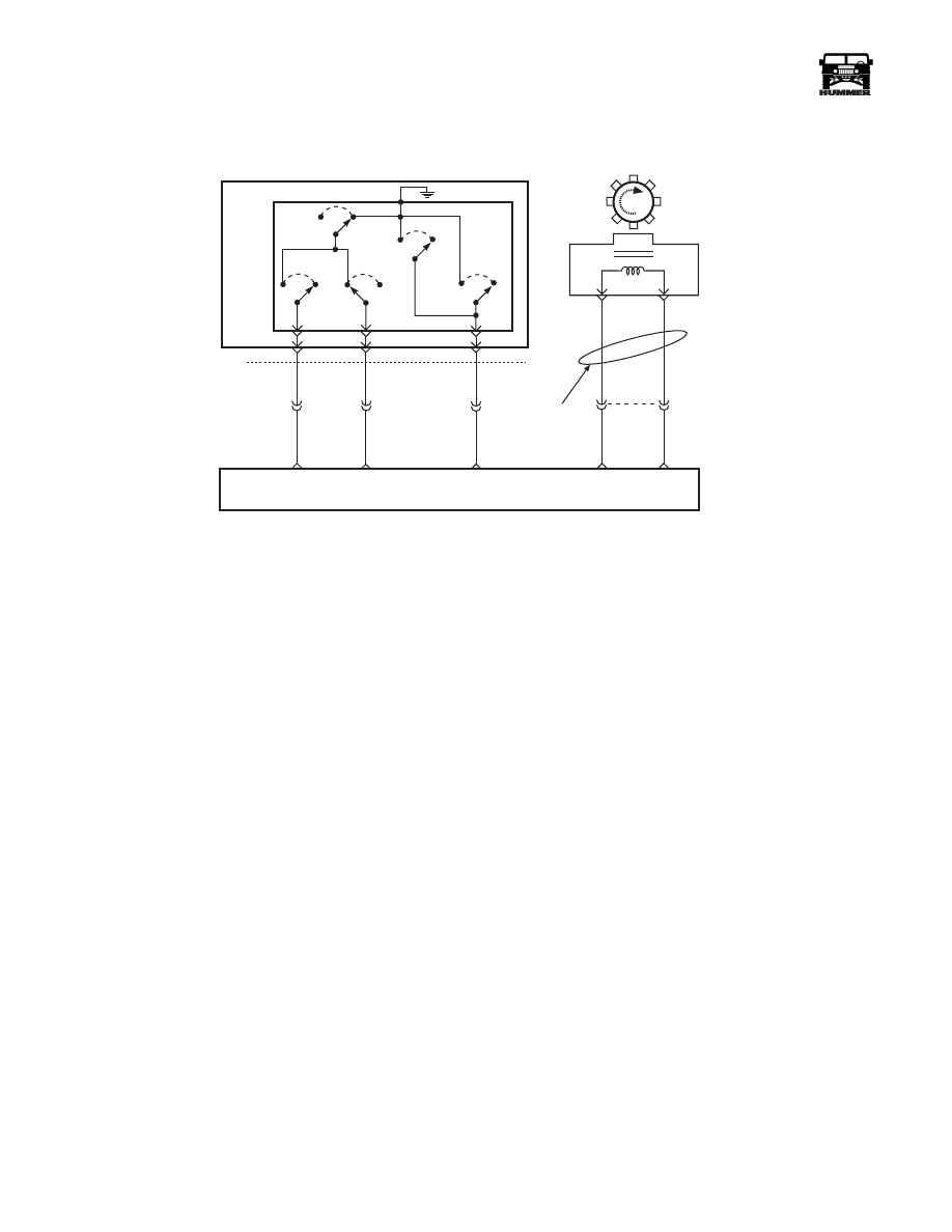
DTC P1810 Pressure Switch Assembly
(PSA) Fault
Circuit Description
The PSA consists of five normally open pressure switches. The
PCM supplies battery voltage to each range signal. By ground-
ing one or more of these circuits through various combinations
of the switches, the PCM detects what manual valve position
has been selected. It then compares actual voltage combina-
tions to a PSA chart in PCM memory.
The PSA switch assembly cannot distinguish between Park and
Neutral because the monitored valve body pressures are identi-
cal in both cases. With the ignition “on” and engine “off,”
Park/Neutral will be indicated. When the transmission 20-way
connector is disconnected, ground potential for the three range
signals is removed, and with ignition “on,” D2 will be indi-
cated.
This DTC detects an invalid state of the PSA sensor or the PSA
circuit by deciphering the PSA inputs.
Conditions For Setting DTC
This DTC will set if any of the following conditions occurs:
Condition 1:
• No system voltage DTC P0560.
• Engine running.
• PCM detects an illegal PSA combination for greater
than 25 seconds.
Condition 2:
• No system voltage DTC P0560.
• No DTCs P0722 or P0723.
• Engine speed is less than 50 rpm for.5 seconds, between
50 and 525 rpm for greater than 0.1 seconds, and than to
greater than 525 rpm and vehicle speed is less than 3
km/h (2 mph).
• PCM detects gear range as D2 before and after start-up.
• Condition exists for greater than 7 seconds and is
checked only at start-up.
Automatic
Transmission
Fluid
Pressure
Manual Valve
Position
Switch
(TFP)
Trans
Range C
Input
Trans
Range B
Input
Trans
Range A
Input
C34
P
R
N
D
E
C
Rev
Switch
Lo
Switch
D2
Switch
D3
Switch
D4
Switch
C32-S
C32-H
C32-K
764 PP
763 DB
762 OR
C29-B4
C29-B5
C29-B6
A / T ISS
High
A / T ISS
Low
Tw i s t e d
P a i r
B
C32-A
B
A
Auto Trans Input Shaft
Speed Sensor
A/T ISS
C27-D1
C27-D11
495 DB
496 GY
POWERTRAIN
CONTROL
MODULE
(PCM)
9-S12-071

___________________________________________
Transmission/Transfer Case 5-105
®
05745159
Condition 3:
• No DTCs P0121, P0122, P0123, P0220, P0221, P0222,
P0223, P0225, P0226, P0227 or P0228.
• No DTCs P0716 or P0717.
• No DTCs P0722 or P0723.
• No 1-2 shift solenoid DTCs P0751 or P0753.
• No 3-4 shift solenoid DTCs P0756 or P0758.
• Engine speed is less 3750 rpm.
• Vehicle speed is greater than 8 km/h (5 mph).
• Throttle angle is greater than 12%.
• Engine torque is between 80 ft/lbs and 450 ft.lb.
• Engine running for more than 5 seconds.
• PSA indicates P/N when ratio indicates less than1.58:1
for more than 10 seconds.
• PSA indicates reverse when ratio indicates D4, D3, D2,
D1 for more than 15 seconds.
• PSA indicates D4, D3, D2, D1 when ratio indicates re-
verse for greater than 15 seconds.
Action Taken When The DTC Sets
• The PCM will command maximum line pressure.
• PCM assumes D4 for PRNDL shift pattern.
• The PCM will freeze shift adapts.
• The PCM will illuminate the warning lamp.
Conditions For Clearing DTC
• For California vehicles, the PCM will turn the lamp off
after three consecutive ignition cycles without a failure
reported.
• The DTC can be cleared using the scan tool. The DTC
will be cleared when the vehicle has achieved 40 warm-
up cycles without a failure reported.
• The PCM will cancel the DTC default actions when the
fault no longer exists and the ignition is cycled “off”
long enough to power down the PCM.
Diagnostic Aids
• Refer to the accompanying chart for the normal range
signals and the illegal combinations.
• Inspect the wiring for poor electrical connections at the
PCM and at the transmission 20-way connector. Look
for possible bent, backed out, deformed or damaged ter-
minals. Check for weak terminal tension as well. Also
check for a chafed wire that could short to bare metal or
other wiring. Inspect for a broken wire inside the insula-
tion.
• When diagnosing for a possible intermittent short or
open condition, move or massage the wiring harness
while observing test equipment for a change.
• This DTC can be falsely set during a fluid fill procedure.
After refilling, cycle key down, start and run vehicle for
20 seconds. Key down and allow the PCM to power
down and then restart the vehicle.
• This DTC can be set falsely by low pump pressure or a
stuck pressure regulator.
• This DTC can be set by a slipping forward clutch as-
sembly. It may allow the PCM to see a 2.08:1 ratio (re-
verse) when the manual valve position is indicated as
D4.
• If any engine DTCs or TP Sensor codes are present di-
agnose and clear these DTCs first. Then check to see if
the transmission DTCs have reset.
Test Description
The numbers below refer to the step numbers on the diagnostic
chart.
2. This test checks the indicated range signal to the man-
ual valve actually selected.
3. This test checks for correct voltage from the PCM to
the transmission 20-way connector.
Expected Readings
“ON” = 0 volts/ “OFF = B+
Range Signal
A
B
C
Park
Rev
Neutral
D4
D3
D2
D1
OFF
ON
OFF
OFF
OFF
OFF
ON
ON
ON
ON
ON
OFF
OFF
OFF
OFF
OFF
OFF
ON
ON
OFF
OFF
Illegal
Illegal
ON
ON
OFF
ON
ON
ON

5-106
Transmission/Transfer Case
___________________________________________
®
DTC P1810 Pressure Switch Circuit Fault
Step
Action
Value
Yes
No
1
Perform following check:
• Transmission linkage (from select lever to the
manual valve) is properly adjusted.
• Fluid check.
Were checks performed?
—
Go to Step 2
—
2
1.
Connect scan tool.
2.
Turn ignition switch to on.
NOTE: Important:
Before clearing DTC(s), use the
scan tool to record “Freeze Frame” and “Failure
Records” for reference, as data will be lost when the
“Clear Info” function is used.
3.
Record the DTC “Freeze Frame” and “Failure
Records.”
4.
Start and run engine at curb idle.
5.
Apply service brake and shift into D1, D2, D3, D4,
N, R, and P.
Does each selected transmission range match the scan
tool “TR Switch” display?
—
Go to Diag-
nostic Aids
Go to Step 3
3
1.
Turn ignition “off.”
2.
Disconnect transmission 20-way connector (addi-
tional DTCs may set).
3.
Connect 05743837 Jumper Harness to engine side
of transmission 20-way connector.
4.
Stop engine then turn ignition back to on.
5.
Using multimeter and Connector Test Adapter Kit,
check voltage at harness connector terminals “N,”
“R,” and “P.”
Is B+ displayed on all three circuits?
—
Go to Step 5
Go to Step 6
4
For circuits that did not indicate B+, check for an open
or short to ground.
Was a problem found?
—
Go to Step 9
Go to Step 6
5
To verify that circuits 762, 763, 764 are not shorted
together, use a fused jumper to ground on each circuit
while monitoring the scan tool “TR Switch” display.
When a range signal circuit is grounded, are the other
range signal circuits affected?
—
Go to Step 7
Go to Step 8
6
Check PCM connector terminals for poor connections.
If no problem is found, replace PCM.
Is the replacement complete?
—
Go to Step 9
—
7
Repair switch wiring as necessary.
Is the repair complete?
—
Go to Step 9
—
8
Replace pressure switch.
Was the PSA replaced?
—
Go to Step 9
—
Нет комментариевНе стесняйтесь поделиться с нами вашим ценным мнением.
Текст