Hummer H1 (2002+). Manual — part 7
_______________
General Information, Lubrication and Maintenance 1-25
¨
05745159
A/C Refrigerant and Compressor Oil
The only refrigerant that can be used is R-134a. No other re-
frigerant is recommended.
The only compressor oil recommended is PAG (polyalkylene
glycol). It is the only oil compatible with refrigerant R-134a.
No other oil is recommended. Any PAG oil used should be
compatible with General Motors specifications.
A/C system capacities are:
¥ 11 fluid ounces (325 ml) of PAG oil
¥ 3.2 lb (1.45 kg) refrigerant
LUBRICATION AND MAINTENANCE ITEMS
Engine Oil Level
The engine oil dipstick is at the driver side of the engine
(Figure 1-18). Correct oil level is to the FULL mark. Accept-
able level is in the crosshatch area below the FULL mark.
Check oil level only when the engine is shut down and the ve-
hicle is on a level surface. Wait one minute after shut down to
check.
Never overfill the engine. The excess oil will be churned into
foam causing oil film breakdown and consequent engine dam-
age.
Figure 1-18: Oil Dipstick Location
Engine Oil and Filter Change
The oil filter is located on the driver side of the engine
(Figure 1-19). A front mounted fill tube is used.
The spin-on oil filter is only removed with a standard band-
type tool. Coat the seal on a new filter with oil and clean the
adapter surface before installation. Tighten the filter by hand.
Replace filter every 3,000 mi (4,800 km).
The oil pan drain plug has a gasket that should be replaced if
cut, cracked, or distorted. Check the gasket seating surface on
the oil pan. Burrs or nicks can be smoothed with a fine tooth
file. Also replace the drain plug if the threads are worn or dam-
aged. Be sure the plug is tightened to required torque of 16 lb-
ft (22 N¥m).
Figure 1-19: Oil Filter/Drain Plug Location
Figure 1-20: Engine Oil Fill Location
OIL DIPSTICK
ADAPTER
OIL PAN
DRAIN PLUG
OIL FILTER
OIL FILLER CAP
1-26
General Information, Lubrication and Maintenance
________________
¨
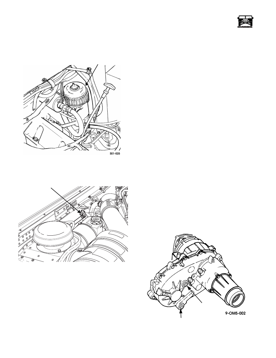
Fuel Filter Service
Replace the filter element every 6,000 mi (9,600 km), or annu-
ally, whichever occurs first (Figure 1-21). See ÒPurging Air
From Diesel FilterÓ (Section 3).
Figure 1-21: Fuel Filter Location
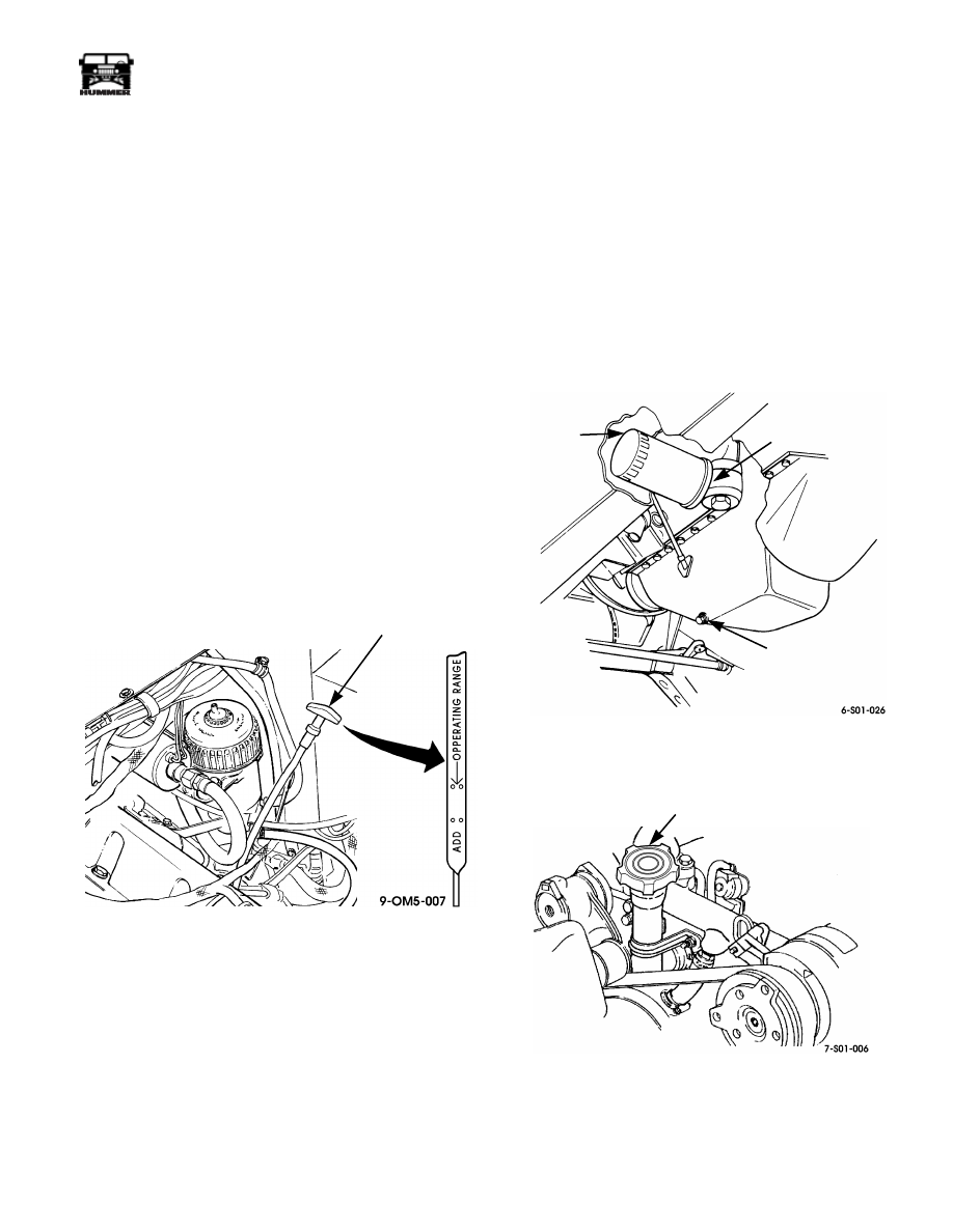
Transmission Fluid
Figure 1-22: Transmission Dipstick Location
Replace the transmission fluid filter each time the fluid is
changed. Refill the transmission with Dexron
¨
III afterward.
Check transmission fluid level at least once each month. Proce-
dure is as follows:
1.
Drive vehicle until transmission ßuid is at normal operating
temperature. Fluid must be hot to obtain accurate reading.
2.
Position vehicle on level surface.
3.
Shift transmission into Park.
4.
Operate engine at curb idle speed.
5.
Remove transmission dipstick and check level (Figure 1-22).
Correct level is within crosshatch marks on dipstick.
6.
If fluid level is too high, remove excess through fill tube
using suction gun and 3/16-in. teflon tubing. If level is
low, check for leaks and, if OK, add fluid in 1-2 ounce
increments until level is correct.
CAUTION: Do not overfill the transmission. The excess fluid
will be churned into foam resulting in overflow from the fill
and vent tubes, slip and flare during upshifts, fluid breakdown
and eventual clutch failure.
7.
Check fluid color and condition. Normal color ranges
from dark red to light pink. Fluid that is dark brown, black,
or orange and full of bubbles indicates a problem that may
require overhaul.
Transfer Case Fluid
Check transfer case fluid level every 3,000 mi (4 900 km), or
semiannually, whichever comes first. Remove fill plug and
gasket. Level should be within 1/2 in. (12.7 mm) of fill plug
opening when transfer case is level. Install fill plug and gasket,
and tighten to 15-25 lb-ft (20-33 N¥m). Change fluid every
12,000 mi (19 000 km) or annually, whichever occurs first
(Figure 1-23).
Inspect rubber plug in the shift rail roll pin access passage lo-
cated near the shift lever for leakage. Replace plug if leakage is
present.
Figure 1-23: Transfer Case Fill/Drain Plug Location
FUEL FILTER
TRANSMISSION
DIPSTICK AND
FILL TUBE
FILL PLUG
DRAIN PLUG

_______________
General Information, Lubrication and Maintenance 1-27
¨
05745159
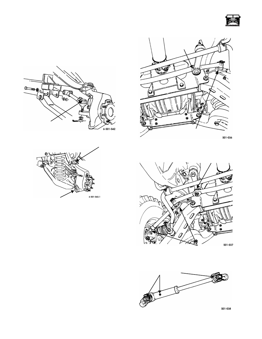
Axle and Geared Hub
Check axle and hub lubricant condition and level every 3,000
mi (4,800 km) or semiannually, whichever occurs first.
Geared hub level should be within 1/2 in. (12.7 mm) of fill
plug opening when lubricant is cold, or to plug level when hot.
Axle level should be within 1/4 in. (6.4 mm) of fill plug open-
ing when lubricant is cold, or to plug level when hot
(Figures 1-24 and 1-25).
Change axle and hub lubricant when contaminated by water or
foreign material.
Use GL-5, SAE 80W-90 or 75W-90 gear lubricant only.
Figure 1-24: Geared Hub Fill/Drain Plug Locations
Figure 1-25: Axle Fill/Drain Plug Locations
Universal and Slip Joint Lubrication
Lubricate U-joints with a multipurpose, NLGI-LB grade chas-
sis grease.
Lubricate propeller shaft universal and slip joints every 3,000
mi (4,800 km), or semiannually, whichever occurs first. Use a
hand operated or low-pressure air powered lubrication gun. If
operating conditions are severe service at 1,000 mi. (1,600 km)
intervals.
The rear propeller shaft U-joints have two grease fitting loca-
tions (Figure 1-26). The front shaft has four fitting locations
(Figure 1-27)
Figure 1-26: Propeller Shaft Lube Points
Figure 1-27: Front Propeller Shaft Lube Points
LUBRICATION POINT
FILL PLUG
DRAINPLUG
LUBRICATION
POINT
FILL PLUG
DRAINPLUG
U-JOINT LUBE FITTINGS
LUBE FITTING
LOCATIONS
LUBE FITTING
LOCATIONS
1-28
General Information, Lubrication and Maintenance
________________
¨
Steering and Suspension Lubrication Points
Lubricate steering and suspension components every 3,000 mi.
(4 800 km), or semiannually, whichever occurs first. If operat-
ing conditions are severe, service at 1,000 mi. (1 600 km) inter-
vals.
Figure 1-28: Ball Joint/Radius Rod Lube Points
Suspension lube points include the upper and lower ball joints
and the rear suspension radius rods (Figure 1-28). Steering lube
points include the tie rod ends, idler arm, steering arm, and in-
termediate steering shaft ( Figure 1-29 through Figure 1-31).
Use a hand operated or low pressure air powered lube gun
filled with a multipurpose chassis grease. NLGI-LB classifica-
tion lubricating grease is recommended.
Figure 1-29: Idler Arm and Tie Rod Lube Points
Figure 1-30: Tie Rod and Steering Arm Lube Points
Figure 1-31: Intermediate Steering Shaft
Lube Points
RADIUS ROD
LUBE FITTING
UPPER BALL
JOINT FITTING
LOWER BALL
JOINT FITTING
IDLER ARM
FITTINGS
TIE ROD END
FITTING (2)
STEERING ARM FITTING
TIE ROD END FITTINGS
LUBE FITTINGS
Нет комментариевНе стесняйтесь поделиться с нами вашим ценным мнением.
Текст