Hummer H1 (2002+). Manual — part 274
_____________________________________________________
PCM/Tech 1 Scan Tool 29
®
05745159
DTC P0117 Engine Coolant Temperature
(ECT) Sensor Circuit Low Voltage
Circuit Description
The engine coolant Temperature (ECT) sensor is a thermistor
that controls signal voltage to the PCM. When the engine is
cold, the sensor resistance is high, therefore the PCM will see
high signal voltage. As the engine warms, sensor resistance be-
comes less and voltage drops. The voltage measured across the
thermistor is interpreted as a temperature. This is a type B
DTC.
Conditions for Setting the DTC
Engine coolant temperature greater than or equal to 151°C
(303°F) for 2 seconds.
Action Taken When the DTC Sets
• High idle
• No TCC
• Shift schedules will be affected.
Conditions for Clearing the MIL/DTC
• The PCM will turn the MIL off after three consecutive
trips without a fault condition.
• A History DTC will clear when forty consecutive
warm-up cycles that the diagnostic does not fail (coolant
temperature has risen 5°C (40°F) from start up coolant
temperature and engine coolant temperature exceeds
71°C (160°F) that same ignition cycle).
• Use of a Scan Tool.
Diagnostic Aids
Check harness routing for a potential short to ground. After en-
gine is started, the coolant temperature should rise steadily to
about 85°C (185°F). refer to “Intermittents” on page 14. A
“skewed” sensor could result in poor driveability complaints.
Test Description
Number(s) below refer to the step number(s) on the Diagnostic
Table.
2. This step determines if P0117 is a hard failure or an inter-
mittent condition.
3. This test will check the PCM and the wiring.
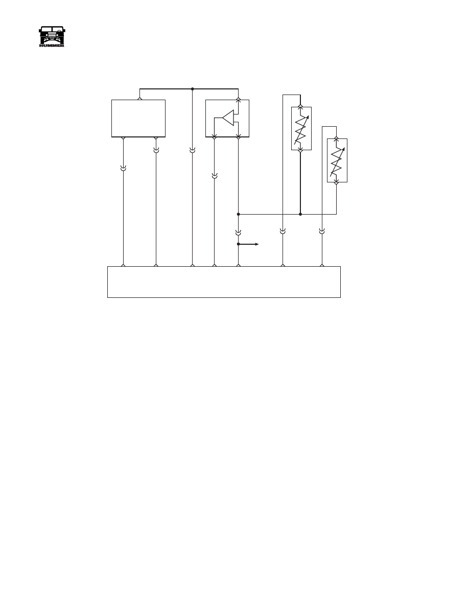
5 VOLT
REFERNCE
CKP
SENSOR
SIGNAL
SENSOR
GROUND
CRANK
SHAFT
POSITION
SENSOR
(CKP)
A
B
B
A
B
B
A
A
C
C
C5-B12
C5-B5
C5-B9
BOOST/
BARO
PRESSURE
SENSOR
INTAKE AIR
TEMPERATURE
SENSOR (IAT)
ENGINE
COOLANT
TEMP
SENSOR
(ECT)
C5-B10
POWERTRAIN
CONTROL
MODULE
CKP
SENSOR
SIGNAL
SENSOR
GROUND
5 VOLT
REFERENCE
BOOST
SENSOR
SIGNAL
SENSOR
GROUND
ECT
SENSOR
SIGNAL
IAT
SENSOR
SIGNAL
C29-A5
359 BK
C5-C4
C5-C5
C27-C1
C27-D13
C27-C14
C29-B12
349 YL
651 PP
350 LG
394 LB
359 BK
C5-B11
TO
TFT
SENSOR
357 TN
354 YL
9-S12-066

30
PCM/Tech 1 Scan Tool
_____________________________________________________
®
DTC P0117 - Engine Coolant Temperature (ECT) Sensor Circuit Low Voltage
Step
Action
Value(s)
Yes
No
1
NOTE:
Before clearing DTC(s) use the Scan tool “Capture Info” to
record Freeze Frame and Failure Record for reference. This data
will be lost when “Clear Info” function is used.
Was the “On-Board Diagnostic (OBD) System Check” performed?
—
Go to Step 2 Go to OBD
System Check
2
1. Scan tool connected.
2. Start the engine.
3. Monitor the ECT display on Scan Tool.
Does the scan tool display ECT greater than or equal to the specified
value?
151°C
(303°F)
Go to Step 3 Go to Step 5
3
1. Turn the engine “OFF.”
2. Turn the ignition “ON.”
3. Disconnect the ECT sensor connector.
Does the scan tool display ECT less than or equal to the specified value?
-30°C
(-22°F)
Go to Step 7 Go to Step 4
4
1. Turn the ignition “OFF”.
2. Using the J–39200, check the resistance across the ECT sensor harness
connector.
Is the resistance at the specified value?
Infinite
Go to Step 8 Go to Step 6
5
DCT is intermittent. If no additional DTCs are stored, refer to “Diagnostic
Aids.” If additional DTCs were stored, refer to those table(s) first.
Are any additional DTCs stored?
—
Go to the
applicable
DTC Table
Go to
Diagnostic
Aids
6
Repair the short to ground in the ECT signal circuit.
Is the action complete?
—
Go to Step 9
—
7
Replace the faulty ECT sensor.
Is the action complete?
—
Go to Step 9
—
8
Replace the faulty PCM.
NOTE:
If the PCM is faulty, the new PCM must be programmed.
Go to PCM replacement and programming procedures.
Is the action complete?
—
Go to Step 9
—
9
1. Using the Scan Tool, select “DTC,” “Clear Info.”
2. Start engine and idle at normal operating temperature.
3. Select “DTC,” “Specific,” then enter the DTC number which was set.
4. Operate vehicle within the conditions for setting this DTC as specified
in the supporting text.
Does the Scan Tool indicate that this diagnostic Ran and Passed?
—
Go to Step
10
Go to Step 2
10
Using the Scan Tool, select “Capture Info,” “Review Info.”
Are any DTC’s displayed that have not been diagnosed?
—
Go to the
applicable
DTC table
System OK
_____________________________________________________
PCM/Tech 1 Scan Tool 31
®
05745159
DTC P0118 Engine Coolant Temperature
(ECT) Sensor Circuit High Voltage
Circuit Description
The Engine Coolant Temperature (ECT) sensor is a thermistor
that controls signal voltage to the PCM. When the engine is
cold, the sensor resistance is high, therefore the PCM will see
high signal voltage. As the engine warms, the sensor resistance
becomes less and the voltage drops. The voltage measured
across the thermister is interpreted as a temperature. This is a
type B DTC.
Conditions for Setting the DTC
• Engine running for at least 8 minutes.
• ECT less than -30°C (-22°F).
• Conditions met for 2 seconds
Action Taken When the DTC Sets
Idle increase
Conditions for Clearing the MIL/DTC
• The PCM will turn the MIL off after three consecutive
trips without a fault condition.
• A History DTC will clear when forty consecutive
warm-up cycles that the diagnostic does not fail (coolant
temperature has risen 5°C (40°F) from start up coolant
temperature and engine coolant temperature exceeds
71°C (161°F) that same ignition cycle).
• Use of a scan tool.
Diagnostic Aids
• Check harness routing for a potential short to ground.
After engine is started, the ECT temperature should rise
steady to about 85°C (185°F). A mis-scaled sensor
could result in poor driveability complaints.
Test Description
Number(s) below refer to number(s) on the diagnostic tables.
2.
This test determines if PO 118 is an intermittent condition.
3. This test will determine if signal circuit is open, or a faulty
PCM.
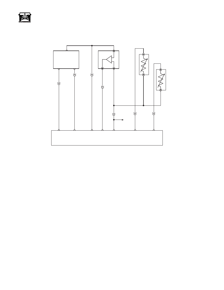
5 VOLT
REFERNCE
CKP
SENSOR
SIGNAL
SENSOR
GROUND
CRANK
SHAFT
POSITION
SENSOR
(CKP)
A
B
B
A
B
B
A
A
C
C
C5-B12
C5-B5
C5-B9
BOOST/
BARO
PRESSURE
SENSOR
INTAKE AIR
TEMPERATURE
SENSOR (IAT)
ENGINE
COOLANT
TEMP
SENSOR
(ECT)
C5-B10
POWERTRAIN
CONTROL
MODULE
CKP
SENSOR
SIGNAL
SENSOR
GROUND
5 VOLT
REFERENCE
BOOST
SENSOR
SIGNAL
SENSOR
GROUND
ECT
SENSOR
SIGNAL
IAT
SENSOR
SIGNAL
C29-A5
359 BK
C5-C4
C5-C5
C27-C1
C27-D13
C27-C14
C29-B12
349 YL
651 PP
350 LG
394 LB
359 BK
C5-B11
TO
TFT
SENSOR
357 TN
354 YL
9-S12-066

32
PCM/Tech 1 Scan Tool
_____________________________________________________
®
DTC P0118 - Engine Coolant Temperature (ECT) Sensor Circuit High Voltage
Step
Action
Value(s)
Yes
No
1
Important:
Before clearing DTC(s) use the scan tool “Capture Info” to
record Freeze Frame and Failure Record for reference, as data will be lost
when “Clear Info” function is used.
Was the “On-Board Diagnostic (OBD) System Check” performed?
—
Go to Step 2 Go to OBD
System Check
2
1. Scan tool connected.
2. Start the engine.
3. Monitor the ECT display on Scan Tool.
Is the ECT display less than or equal to the specified value?
-30°C
(-22°F)
Go to Step 3 Go to Step 5
3
1. Turn the engine “OFF.”
2. Turn the ignition “ON.”
3. Disconnect the ECT sensor connector.
4. Jumper the ECT harness terminals together.
Does the scan tool display ECT greater than or equal to the specified
value?
151°C
(303°F)
Go to Step 6 Go to Step 4
4
Jumper the ECT sensor signal circuit to a known good ground. Does the
scan tool display a ECT greater than the specified value?
151°C
(303°F)
Go to Step 7 Go to Step 8
5
DCT is intermittent. If no other DTC(s) are stored, go to “Diagnostic
Aids”.
Are there other DTCs stored?
—
Go to
applicable
DTC Table
Go to
Diagnostic
Aids
6
Inspect the sensor connector and PCM connector for a proper connection.
Was a problem found?
—
Go to Step 9
Go to Step 10
7
Check the ECT sensor ground circuit for an open between the ECT sensor
and the PCM.
Was a problem found?
—
Go to Step 9
Go to Step 11
8
Check the ECT sensor signal circuit for an open between the ECT sensor
and the PCM.
Was a problem found?
—
Go to Step 9
Go to Step 11
9
Repair the circuit as necessary.
Is the action complete?
—
Go to Step
12
—
10
Replace the faulty ECT sensor.
Is the action complete?
—
Go to Step
12
—
11
Replace the faulty PCM. NOTE: If the PCM is faulty, the new PCM must
be programmed. Go to PCM replacement and programming procedures.
Is the action complete?
—
Go to Step
12
—
12
1. Using the Scan Tool, select “DTC”, “Clear Info”.
2. Start engine and idle at normal operating temperature.
3. Select “DTC”, “Specific”, then enter the DTC which was set.
4. Operate vehicle within the conditions for setting this DTC as specified
in the supporting text.
Does the Scan Tool indicate that this diagnostic Ran and Passed?
—
Go to Step
13
—
13
Using the Scan Tool, select “Capture Info”, “Review Info”.
Are any DTC’s displayed that have not been diagnosed?
—
Go to
applicable
DTC table
System OK
Нет комментариевНе стесняйтесь поделиться с нами вашим ценным мнением.
Текст