Hummer H1 (2002+). Manual — part 104
______________
Wheels and Tires/Central Tire Inflation System (CTIS) 6-31
®
05745159
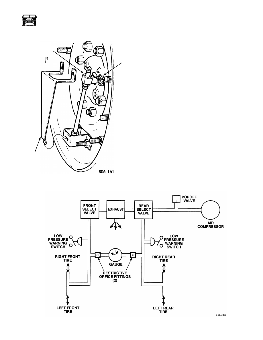
Figure 6-51: Quick-Disconnect Tab
CTIS TROUBLESHOOTING
The following pages contain troubleshooting information for
locating and correcting mechanical, pneumatic, and electrical
problems that may develop with the CTIS.
Electrical Troubleshooting
Symptoms are listed for system malfunctions, and procedures
and corrections are diagramed to assist service technicians.
Figure 6-52: Pneumatic Diagram for Central Tire Inflation System
TUBE SHIELD
QUICK-
VALVE
DISCONNECT
ASSEMBLY
VALVE
SPINDLE
NUT

6-32
Wheels and Tires/Central Tire Inflation System (CTIS)
_______________
®
CTIS AIR LEAK TROUBLESHOOTING
This section contains troubleshooting information for locating
and correcting air leaks within the Central Tire Inflation Sys-
tem.
WARNING: CTIS air system components are subject
to high pressure. Always relieve air pressure before
loosening or removing air system component(s) by dis-
connecting the quick-disconnect valve assemblies at
each wheel end. Failure to follow this warning may re-
sult in serious personal injury.
CTIS Troubleshooting Checklist
1.
Fill all tires to at least 40 psi (270 kPa) using the on-board
compressor or shop air source.
2.
Note the needle positions on the air gauge. If the needles
are not even, line them up by inflating the lower pressure
tires. Then return the inflate/deflate switch to OFF.
NOTE: The tires are isolated from the rest of the system so
that the areas between the compressor selector valve and
geared hubs and selector valve can be isolated and checked.
3.
Isolate each tire and wheel assembly by disconnecting
each quick-disconnect valve.
4.
After tires have been isolated, measure and record each
tire’s air pressure.
5.
After a minimum of 10 minutes, check to see if the air
gauge needles have moved.
NOTE: Leaks can be detected by using soapy water, but com-
mercially available leak detection liquids such as “Gaz-Tec”
work best. Most leaks can be corrected by tightening fittings.
Replace the fittings or air lines only when necessary.
6.
Determine if the front, rear, or both air systems have
leaked. If a leak is detected, concentrate on that area and
follow the appropriate troubleshooting chart.
• Geared Hubs, Seals, and Fittings - Chart 1
• Deflate Valve Area - Chart 2
• Under Vehicle Air Leak - Chart 3
7.
After checking and repairing leak points, place the selector
switch in the BOTH position.
8.
Note the gauge needle positions. Reposition or re-inflate
to align the needles.
9.
Wait at least two minutes and check to see if the needles
have moved. If movement is detected, concentrate on
detecting the leak point. Follow Refer to Troubleshooting
Chart 4 – Air Compressor Leak Test in this Section..
NOTE: If tires were hot, air loss may be a result of the tires
cooling down. If this is the case, all tires should lose about the
same amount of air.
10. Check the air pressure in each tire and compare it to the
information taken earlier. Note any air pressure loss and
concentrate on that tire position. Refer to Troubleshooting
Chart 5– Tire and Quick-Disconnect Valve in this
Section..
If no air loss is detected, there may be a small leak which will
require an overnight evaluation.
NOTE: Always complete the entire troubleshooting procedure
to ensure that all potential leak points have been corrected.
Verification
After completing the troubleshooting procedure, verify the sys-
tem by repeating the CTIS Troubleshooting checklist steps.
WARNING: CTIS air system components are subject
to high pressure. Always relieve air pressure before
loosening or removing air system components(s) by dis-
connecting quick-disconnect valve assemblies at each
wheel end. Failure to follow this procedure may result
in serious personal injury.

______________
Wheels and Tires/Central Tire Inflation System (CTIS) 6-33
®
05745159
Inspect the steering arm cover,
connector, and tube for damage.
Use a soap and water solution or a
commercial leak detection product
around the connector and steering
arm cover.
Damage is found
Replace the con-
nector or tube.
Air is leaking around the con-
nector or tube end.
Tighten the connec-
tor, hose clamp or
tube fitting.
Remove the connector from the
tube and steering arm cover. In-
spect connector and tube fitting
for damage (frays, stripped
threads, cracks, or breaks).
Leak continues
Damage is found
Apply new thread sealant
and install connector to
steering arm cover and
tube fitting or tube.
Air is leaking around steering arm
cover.
Steering arm cover seal or exten-
sion may need replacement. Re-
move steering arm cover and
inspect the seal for damage
(Figure 6-78).
Damage is found
If air is in hub, re-
place seal.
Remove the vent line and deter-
mine if air is escaping. If so, steer-
ing arm cover seal is damaged.
Loose Component
Replace seal
if damaged
Replace part
if damaged
Troubleshooting Chart 1 – Geared Hubs, Seals and Fittings

6-34
Wheels and Tires/Central Tire Inflation System (CTIS)
_______________
®
Inspect the deflate valve and con-
nections for damage (Figure 6-65).
Use a soap and water solution to
check for leaks.
Air is escaping from the
dust excluder or the seams
on the Deflate Valve
(Figure 6-66).
Replace the
deflate valve.
Air is escaping from the
sides of the check valve.
Replace the
check valve.
Tighten all suspect connections. If this fails to
seal the air leak, take the connections apart, clean,
apply new sealant, and tighten.
Leaks
Troubleshooting Chart 2 – Deflate Valve Area
Follow the CTI lines under the vehi-
cle. Inspect for damage. Use a soap
and water or commercial leak detec-
tion solution to detect air leaks.
Tighten all suspect connectors. If this fails to stop the air leak, re-
move the suspect part (elbow, fitting or connector) and inspect
the threads for stripping. Clean, apply new pipe sealant, and in-
stall into the CTI system.
Troubleshooting Chart 3 – Under Vehicle Air Leak
Check the relief valve to en-
sure air is not leaking from
the relief valve stem area.
Replace the
relief valve.
Air is
leaking
If air is leaking from a fitting, tee, elbow or
tube connection, tighten the part. If leak
persists, remove the CTI part, clean, apply
new sealant to the threads and install the
CTI part.
Air is
leaking
Troubleshooting Chart 4 – Air Compressor Leak Test
Inspect all fittings, tees, valves and
hoses connected to the compressor
(Figure 6-53). Use soap and water or
commercial leak detection product to
detect leaks.
Нет комментариевНе стесняйтесь поделиться с нами вашим ценным мнением.
Текст