Hummer H1 (2002+). Manual — part 99

______________
Wheels and Tires/Central Tire Inflation System (CTIS) 6-11
®
05745159
2.
Inspect inner rim for cracked, broken, rusted, pitted, bent,
or loose studs, and studs with damaged, mutilated, or
deformed threads. Replace defective parts (Figure 6-19).
Figure 6-19: Wheel Half Stud
Installation
1.
Align stud with splines in inner rim and drive stud into
inner rim until stud shoulder seats against inner rim
(Figure 6-19).
2.
Repeat step 1 for all studs being replaced.
CAUTION:
Tighten locknuts gradually to avoid bent and bro-
ken studs, or damage to wheel components will result.
3.
Install locknuts on new studs.
NOTE:
After replacing broken stud(s), all wheel locknuts
must be re-torqued.
4.
Tighten locknuts to 85 lb-ft (115 N•m) in sequence shown
(Figure 6-20).
5.
Tighten locknuts to 125 lb-ft (170 N•m) in sequence
shown.
Figure 6-20: Wheel Half LockNut Tightening Se-
quence
6.
Check wheel assembly for gaps at each stud. Use a 0.0015
in. (0.038 mm) thickness gauge to detect gaps. If gaps are
detected, disassemble and reassemble wheel assembly and
recheck for gaps. If gaps are still detected, replace outer
rim half.
WARNING: Never inflate a wheel assembly without
having checked wheel locknut torques to ensure the
wheel locknuts are tightened to specifications. An as-
sembly with improperly tightened locknuts could sepa-
rate under pressure, resulting in serious injury or
death.
WARNING: Always use a tire inflation cage for infla-
tion purposes. Stand on one side of the cage during in-
flation, never directly in front. Keep hands out of cage
during inflation. Inflate assembly to recommended
pressure, using a clip-on air chuck. Do not exceed 50
psi (345 kPa) cold inflation pressure. Failure to follow
these instructions may result in serious injury or death.
7.
Place wheel in safety cage and inflate tire to the
recommended tire pressure.
8.
Check for leaks around rim edges and valve bore with
soapy water.
9.
Install wheel on vehicle.
STUD
S06-103.1
4
3
11
12
7
8
1
2
5
6
10
9

6-12
Wheels and Tires/Central Tire Inflation System (CTIS)
_______________
®
RUNFLAT COMPRESSOR BELT REPLACEMENT
Installation
Figure 6-21: Runflat Compressor Belt Replacement
NOTE: Belt overlap is to be positioned so that you have equal
amount of belt on each side of the worm gear shaft assembly.
Perform steps 1 and 2 for crank handle runflat compressor.
1.
Install belt on compressor with bolt and locknut
(Figure 6-21).
2.
Loop free end of belt around retaining bracket
(Figure 6-22).
Figure 6-22: Runflat Compressor Belt Installation
TIRE, ONE-PIECE ALUMINUM WHEEL
(OPTION), AND TWO-PIECE RUNFLAT SER-
VICE
CAUTION: It is not recommended mixing one-piece wheel and
runflat assemblies and two-piece take-apart wheel and runflat
assemblies on the same vehicle. Runflat profiles differ between
the two types of wheel assemblies.
Disassembly
1.
Remove the center cap.
If the vehicle is equipped with a Central Tire Inflation System
(CTIS), perform steps a and b.
a.
Release the quick disconnect fitting located at the
center of the geared hub spindle on all four wheels.
b.
Remove the 3/4 inch brass fitting from the center of
the geared hub spindle on the wheel(s) to be worked
on.
2.
Remove wheel/tire assembly from vehicle.
3.
Inspect geared hub spindle studs for bending, looseness, or
stripped threads. Replace if damaged.
4.
Inspect lug nuts for fatigue, stripped threads, or other
damage. Replace if damaged.
5.
Remove valve cap and core from air valve and deflate tire.
Run a piece of wire through air valve to ensure it is not
plugged.
WARNING: Balance weights contain lead. Wash hands
after handling.
6.
Remove balance weights from wheel if present. Discard
balance weights.
7.
Install wheel/tire assembly on tire machine.
8.
Using tire machine break loose both tire beads.
9.
Lubricate outside tire bead and use tire machine to remove
bead from wheel flange.
10. Pull tire bead up away from wheel to expose runflat
assembly. This can be accomplished with pry bars or a
bead spreader devise (Figure 6-23).
COMPRESSOR
BELT
BELT
RETAINING
BRACKET
______________
Wheels and Tires/Central Tire Inflation System (CTIS) 6-13
®
05745159
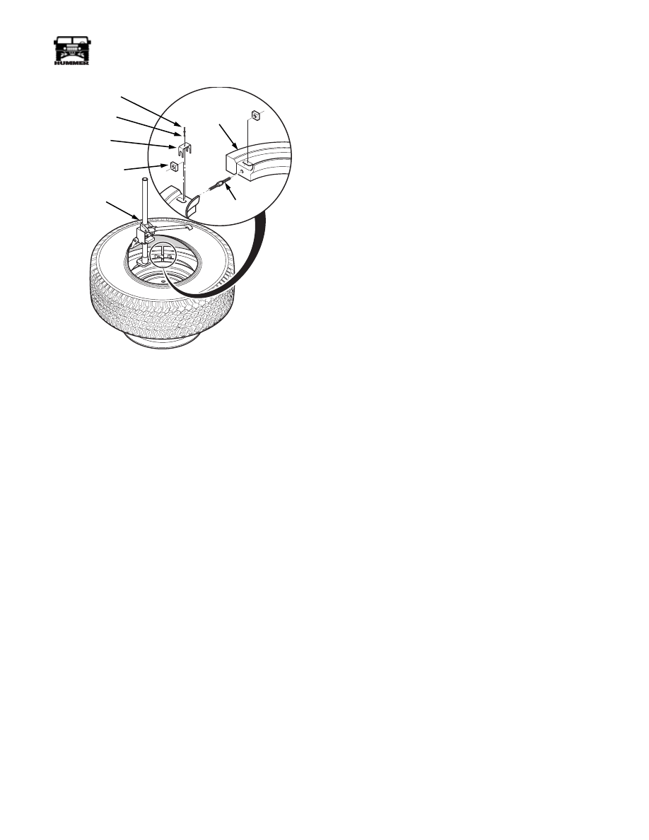
Figure 6-23: Runflat Removal
11. Remove the retaining screw,washer and crossbolt locking
clip (Figure 6-24).
12. Loosen and remove the crossbolt and square nuts securing
the runflat halves together.
13. Repeat steps 11 through 13 for opposing fastener
assembly.
14. Reach inside the tire and remove runflat halves from the
tire.
15. Lubricate the tire bead and remove the tire from the wheel.
Inspection and Cleaning
Cleaning
1.
Remove any existing lubricant that has been applied to the
inside of the tire, using tire buffing solution.
2.
Clean all wheel, runflat and tire parts using tire buffing
solution.
3.
Dry all wheel, runflat and tire parts. Ensure inside of tire
and all wheel, runflat and tire parts are free of any runflat
lubricant, dirt, rust or moisture.
Tire Inspection
1.
Inspect tire for the following conditions or defects.
Replace tire if damaged.
a.
Inspect inside of tire for cord or belt separation and
inner crown area damage.
b.
Inspect tire bead for damage.
c.
Check for protruding objects inside tire which may
not be visible from outside. If tire is damaged, repair
with external (05710215) or internal (05710216) tire
repair kit.
d.
Check tread depth on tire. Tread should not be worn
below level of wear bars. Markings on the side of the
tires (e.g., the letters “TWI” or a triangle) show the
location of wear bars. Replace tire if tread is worn
below bars or 3/32 inch (2.38mm).
Runflat Inspection
1.
Inspect runflat for the following conditions or defects.
Replace runflat(s) if damaged.
a.
Splitting or separation of rubber from composite
material.
b.
Wear or damage of outside rim or centering flange.
c.
Excessive chafing or particles of the tire’s steel belt
embedded into runflat assemblies.
d.
Crossbolts for stress fatigue, cracks or thread damage.
e.
Square nuts for stress fatigue, cracks or other damage.
f.
Crossbolt locking clip and retaining screw for
damage.
Wheel Inspection
1.
Inspect wheel for the following conditions or defects.
Replace wheel if damaged.
a.
Cracked or bent.
b.
Mounting bolt holes for stress fatigue, oversized
holes, or other damage.
c.
Wheel flange for stress fatigue, deformation or other
damage.
d.
Valve and insert for cracks or deterioration. Replace
these items if damaged.
SID
EF
A
CI
NG
OU
TW
AR
DS
00-S06-010
LOCKING
CLIP
CROSSBOLT
SQUARE
NUT
RETAINING
SCREW
RUNFLAT
BEAD
SPREADER
WASHER
6-14
Wheels and Tires/Central Tire Inflation System (CTIS)
_______________
®
Assembly
NOTE: If tires are to be replaced allow new tires to reach
room temperature (above 60°) before mounting. This will
make the tire more pliable and easier to work with.
CAUTION: During assembly or disassembly, loose parts
which are dropped inside the wheel/tire assembly must be re-
moved. Failure to do so could result in damage to wheel/tire
assembly.
1.
Apply one tube (approximately 11 ounces) of runflat gel
lubricant to inside crown area of tire. Using clean brush,
evenly spread gel lubricant 4 to 5 inches wide on inner
crown area.
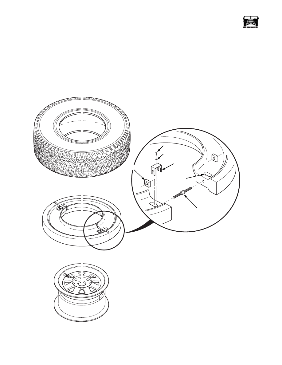
Figure 6-24: Runflat Installation
SIDE
FA
CIN
G
OU
TW
AR
DS
00-S06-012
CROSS BOLT
SQUARE NUT
LOCKING
CLIP
SCREW
RECESS
WASHER
Нет комментариевНе стесняйтесь поделиться с нами вашим ценным мнением.
Текст