Hummer H1 (2002+). Manual — part 14
____________________________________________________________________
Engine 2-17
¨
05745159
Turbocharger Removal
1.
Remove front console, rear console, engine cover, and dis-
connect related wiring and A/C ducting.
2.
Remove turbocharger heat shielding.
3.
Loosen clamps attaching turbocharger inlet tubes to
exhaust manifolds and turbocharger. Then work tubes
loose and remove them.
4.
Remove air duct and hoses connecting turbocharger to air
cleaner.
5.
Disconnect vacuum hose at wastegate vacuum actuator.
6.
Loosen bolts that attach manifold crossover to left and
right manifold halves.
7.
Prop manifold crossover up with blocks.
8.
Lift, turn and tilt turbocharger to remove it (Figure 2-10).
Do not pry or force it off the engine.
Turbocharger Installation
1.
Install new O-ring seal on turbocharger manifold outlet.
Do not reuse old O-ring as leakage may occur.
2.
Clean gasket surfaces of intake manifold and crossover
housing.
3.
Mount turbocharger on engine and install bolts that secure
it to engine block.
4.
Tighten crossover housing bolts.
5.
Install air inlet duct and hose and connect vacuum pump to
actuator.
6.
Install turbocharger inlet tubes. Tighten flange clamps that
secure tubes to manifolds and turbocharger to 71 lb. in.
(8 N¥m) torque.
7.
Install turbocharger and exhaust pipe heat shielding.
8.
Install engine cover, console, and ducting
.
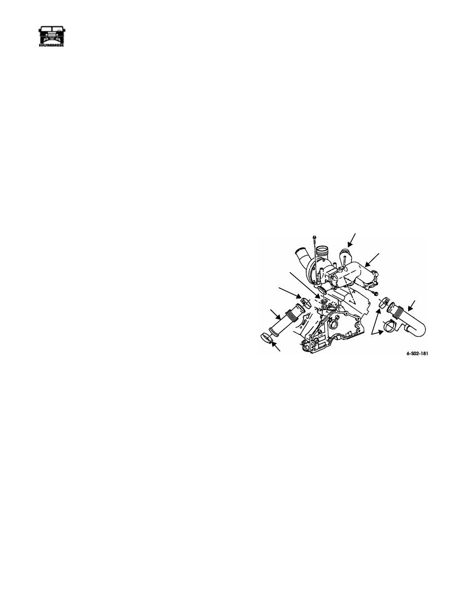
Figure 2-10: Turbocharger Mounting
VACUUM
TURBOCHARGER
ACTUATOR
OIL
INLET
PIPE
PIPE
CLAMP
PIPE
CLAMP
PIPE
CLAMP
SEAL
INLET
PIPE

2-18
Engine
_____________________________________________________________________
¨
Turbocharger Diagnosis
PROBLEM
POTENTIAL CAUSE
CORRECTION
Low Power Poor
Acceleration
(Black smoke not
evident at 1/2 to
wide open
throttle)
1.
Lean fuel mixture caused by insufÞcient fuel
volume or pressure.
1. Problem is in fuel delivery system. Check fuel
supply pump pressure, look for leaks in lines and
at Þttings, plugged fuel Þlter, accelerator cable
problem, injection pump problem. Refer to low
power information in guides for standard diagno-
sis.
Low Power,
Poor Accelera-
tion (Black
smoke evident
at 3/4 to wide
open throttle)
1.
Air Þlter plugged.
2.
Restriction in air intake duct to turbocharger
compressor wheel.
3.
Air leak in turbocharger compressor inlet and
outlet ducts. May be accompanied by high
pitch whine indicating system air leak.
4.
Loss of vacuum to wastegate actuator, or actu-
ator is damaged.
5.
Air leak at intake manifold.
6.
Exhaust leak between cylinder head ports and
turbine inlet of turbocharger.
7.
Turbocharger damaged internally.
8.
Fuel system problem (over-rich mixture).
1. Replace Þlter.
2. Remove and inspect duct components. Remove/
repair any restrictions.
3. Disassemble, inspect, repair worn, damaged,
loose parts.
4. Check vacuum supply. Replace hose and Þttings
if necessary. If OK, use hand operated vacuum
tester to check actuator operation. Replace actu-
ator or vacuum pump, as required.
5. Tighten loose bolts. Or, remove manifold and
replace gaskets if necessary.
6. Check exhaust manifolds pipes, and turbo-
charger connections for leaks. Replace damaged
components, tighten loose fasteners.
7. Remove and inspect turbocharger. Replace if
compressor/turbine wheels, or other internal
components are damaged.
8. Refer to low power information in standard diag-
nosis.
Turbocharger
Noise
1.
Obstruction in air intake or outlet systems
may cause high pitch whine.
2.
Compressor/turbine impeller contacting hous-
ing, or other internal damage. May be accom-
panied by vibration.
1. Disassemble and clear blockage, or restriction.
2. Replace turbocharger.
Blue Exhaust
Smoke with
Warm Engine
Only
1.
InsufÞcient intake air volume.
2.
Partially plugged oil drain tube.
3.
Oil Leaking past worn compressor or turbine
side seals.
4.
Engine problem caused by worn rings, or
valve seals.
1. Disassemble, inspect, and clear any restrictions.
Replace damaged, worn ducting parts.
2. Remove and clear tube. Replace tube if fully
plugged, pinched, or kinked.
3. Replace turbocharger.
4. Overhaul cylinder heads or engine as needed.
____________________________________________________________________
Engine 2-19
¨
05745159
DIESEL ENGINE IN-VEHICLE SERVICE
General Information
The repair procedures described in this section cover engine
service that can be performed in the vehicle. Engine removal is
not required.
Left/Right Orientation
Left/right orientation throughout this section is from the driver
seat. A left side location refers to the driver side of the vehicle
and a right side location to the passenger side.
ENGINE MOUNTING BRACKET/INSULATOR
Removal
1.
Remove fan and clutch as assembly.
2.
Remove nuts/bolts attaching front propeller shaft center
bearing to bracket.
3.
Mark front propeller shaft U-joint and yoke position with
paint or chalk. Then remove front propeller shaft and
center bearing as assembly.
4.
Remove bolts attaching starter cable bracket to engine.
Move bracket aside for working clearance.
5.
Remove bolts/nuts attaching transmission and mount to
transmission crossmember (Figure 2-11).
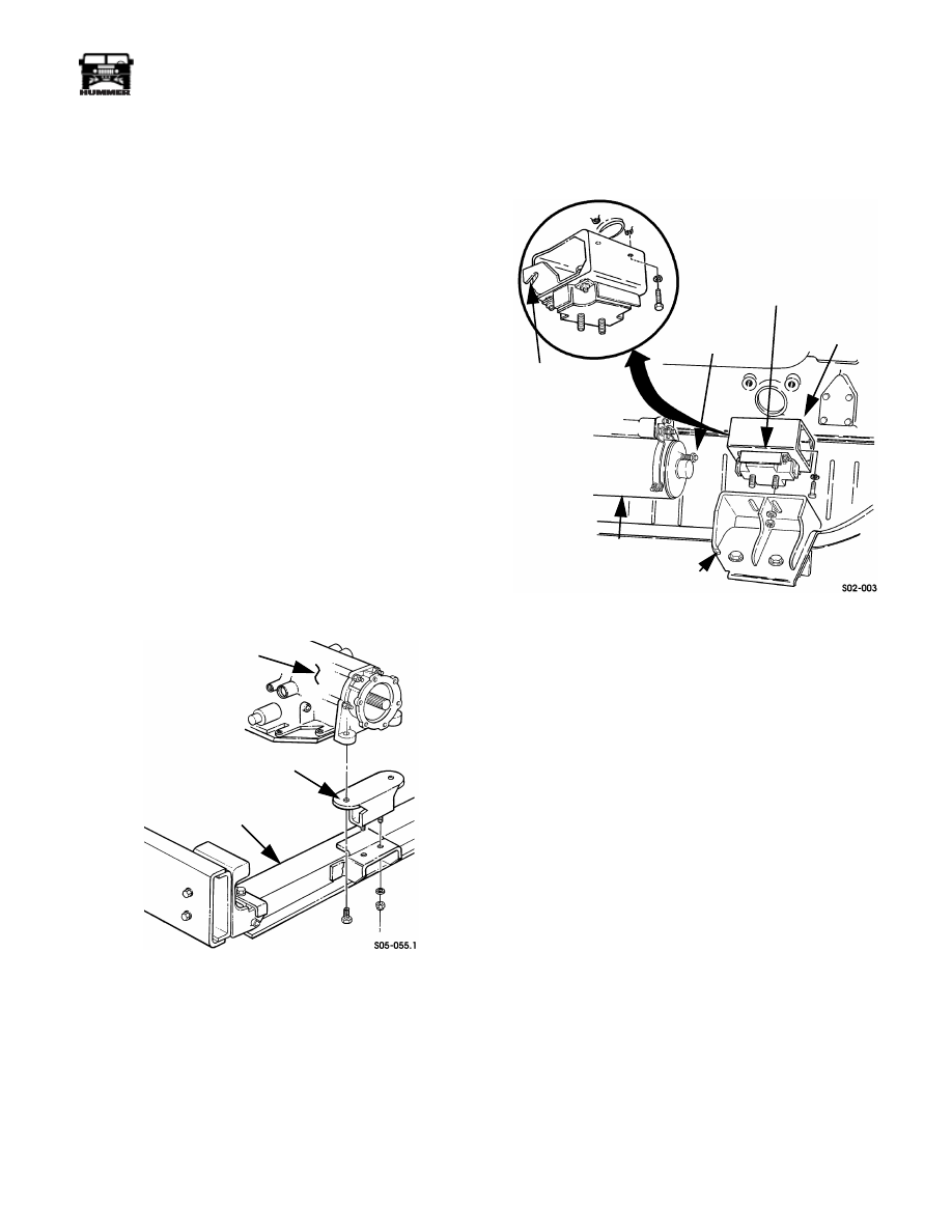
Figure 2-11: Transmission-To-Crossmember
Mounting
6.
Disconnect transmission and transfer case shift rods at
shift lever arms.
7.
Disconnect exhaust pipes, brackets, or hangers as needed.
8.
Support engine with floor jack and wood block, or safety
stand if vehicle is on hoist. Position block or stand under
pan rail at rear main.
9.
Remove nuts/bolts attaching insulators, or brackets to
engine and frame.
10. Remove nut securing engine bracket to stud on starter
motor (Figure 2-12).
11. Raise engine enough to remove insulator, or bracket
(Figure 2-12).
Figure 2-12: Engine Mounting Bracket and Insulator
(Driver Side)
TRANSMISSION
TRANSMISSION
MOUNT
TRANSMISSION
CROSSMEMBER
STARTER
BRACKET
STARTER
FRAME BRACKET
ENGINE
BRACKET
INSULATOR
STUD
AND
NUT
2-20
Engine
_____________________________________________________________________
¨
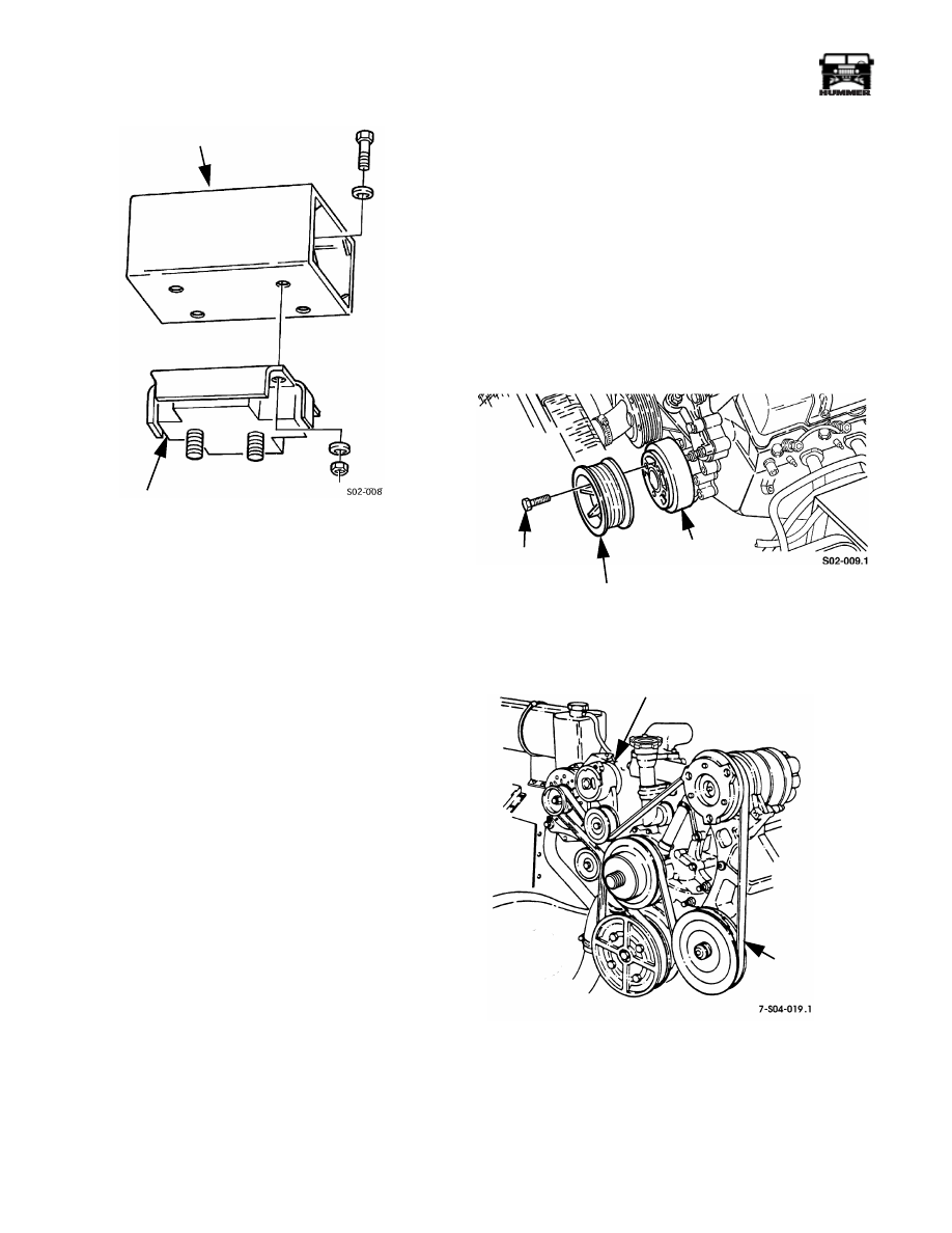
Figure 2-13: Engine Bracket and Insulator
Assembly
Installation
12. Position insulator on engine bracket (Figure 2-13).
13. Install engine bracket and insulator. Tighten engine
bracket-to-block bolts to 30 lb-ft (41 N¥m) torque. Tighten
insulator stud nuts to 90 lb-ft (122 N¥m) torque.
14. Install nut that secures engine bracket to stud on starter
motor (Figure 2-12). Tighten nut to 24 lb-ft (33 N¥m)
torque.
15. Align and install bolts/nuts that attach transmission to
transmission crossmember (Figure 2-11).
16. Connect transmission and transfer case shift rods to floor
shift levers. Use new cotter pins to secure shift rod
trunnions to shift lever arms.
17. Align and install front propeller shaft and center bearing.
Tighten center bearing attaching bolts to 60 lb-ft (81 N¥m)
torque. Tighten U-joint clamp strap nuts to 13-18 lb-ft (18-
24 N¥m) torque.
18. Install starter cable bracket.
19. Connect exhaust pipes, brackets, or hangers if loosened/
removed for service access.
20. Install fan and clutch.
CRANKSHAFT PULLEY
Removal
1.
Loosen (but do not remove) crankshaft pulley bolts
(Figure 2-14).
2.
Remove serpentine accessory drive belt as follows:
a.
Loosen drive belt by rotating belt tensioner in
counterclockwise direction (Figure 2-15). Use 1/2 in.
drive breaker bar to rotate pulley.
b.
Slide belt off tensioner and other pulleys. Then re-
move belt.
3.
Remove crankshaft pulley bolt and remove pulley.
Figure 2-14: Crankshaft Pulley Mounting
Figure 2-15: Serpentine Belt Tensioner Location
ENGINE BRACKET
INSULATOR
TORSIONAL
DAMPER
CRANKSHAFT
PULLEY
PULLEY
BOLT (4)
BELT TENSIONER
SERPENTINE
BELT
Нет комментариевНе стесняйтесь поделиться с нами вашим ценным мнением.
Текст