Hummer H1 (2002+). Manual — part 38

___________________________________________
Fuel, Emissions, and Exhaust 3-13
®
5745159
Low Temperature—High Resistance Test
1.
Connect scan tool and start engine.
2.
Note indicated temperature:
• If temperature is normal, problem is with sensor wires
and connections.
• If temperature is at or above 266° F (130° C), continue
with test. Disconnect sensor wires and note scan tool
reading:
• If temperature now reads -22° F (-30° C), sensor has
failed.
• If temperature is OK, problem is faulty sensor ground,
reference wire shorted to ground, or PCM has fault.
Figure 3-11: Coolant Temperature Sensor Circuit
Baro Sensor
The baro sensor on turbo diesel models is used to send a baro-
metric pressure signal to the PCM. The signal is in the form of
a voltage that is interpreted by the PCM. The sensor signal is to
adjust fuel metering and timing at different altitudes. The scan
tool is used for baro sensor testing.
Engine Shut-Off Solenoid Test
A shut-off solenoid failure can result in run-on, or a no start
condition. The failure may be with the solenoid, or with the re-
lated wiring (Figure 3-12).
1.
Connect the scan tool.
2.
Select Miscellaneous Tests, Engine Outputs, Injection
Pump, then Engine Shutoff.
3.
Use the arrow keys to toggle the solenoid Off/On and
listen for the solenoid to activate or click.
4.
If the solenoid does not activate, perform wiring tests with
a DVOM (Figure 3-12).
5.
If the wiring tests OK, replace the solenoid.
Figure 3-12: Engine Shut-Off Solenoid Circuit
Engine Shut-Off Solenoid Replacement
Removal
1.
Disconnect the electrical connector from the ESO solenoid
(Figure 3-13).
NOTE:
Remove any debris from the ESO mounting surface
on the injection pump before servicing the ESO solenoid. This
will prevent contaminants from getting into and damaging the
injection pump.
2.
Remove the solenoid (style may vary) and O-ring from the
injection pump housing.
Figure 3-13: ESO Solenoid Replacement
COOLANT
TEMPERATURE
SENSOR
PCM
ENGINE
SHUTOFF SOLENOID
TO IGNITION
SWITCH
F/SOL
20 AMP
PCM
SOLENOID
CONTROL
TO
FUEL
SOLENOID
DRIVER
ESO
SOLENOID
TO HARNESS
CONNECTION
INJECTION
PUMP

3-14
Fuel, Emissions, and Exhaust
___________________________________________
®
Installation
3.
Install the O-ring seal above the threads at the bottom of
the new solenoid (Figure 3-14).
4.
Install the replacement solenoid into the injector pump
housing and torque to 19 lb-ft (25 N•m).
5.
Connect the electrical connector to the ESO solenoid.
6.
Start the engine and check for leaks.
Figure 3-14: Two Styles Of Solenoids
Optical/Fuel Temperature Sensor Tests
The optical/fuel temperature sensor supplies three signals to
the PCM for fuel control and timing. A high resolution signal
helps determine injection timing and fuel control. A pump cam
signal provides reference pulses that monitor and help deter-
mine injection timing. The fuel temperature signal helps the
PCM determine pump advance or retard requirements and fuel
flow. The sensor is located at the top of the injection pump ad-
jacent to the fuel shut-off solenoid.
A fault in the optical sensor or related wiring will produce fast
idle and performance problems. A problem will cause a high
resolution circuit fault, or a cam reference pulse error fault.
The sensor can be checked with a scan tool and a voltmeter as
follows:
High Resolution Fault Test
1.
Turn ignition off.
2.
Disconnect sensor harness connector.
3.
Turn ignition on.
4.
Connect voltmeter to sensor terminal A, of the harness,
and to ground (Figure ).
• If meter indicates 5 volts, continue with test.
• If meter indicates zero voltage, look for open/short in
wire to PCM 5 volt reference terminal, connector, or
PCM.
5.
Connect volt/ohmmeter to a good engine ground and to
sensor ground terminal D:
• If resistance is .2
W
or less, proceed to next test step.
• If resistance is greater than .2
W
, problem is with ground
wire, connector, or sensor.
Fuel Solenoid and Solenoid Driver
The solenoid and driver provide the fuel injection metering to
the individual injectors. The driver receives the PCM com-
mand and transmits it to the solenoid which controls the actual
injection process.
The solenoid driver also returns a pulse width signal back to
the PCM. This signal informs the PCM that injection has taken
place. The pulse width signal time is in milliseconds.
A fault in either component will cause an injection pulse width
Figure 3-15: Optical/Fuel Temperature Sensor Circuit
WIRE
HARNESS
O-RING
___________________________________________
Fuel, Emissions, and Exhaust 3-15
®
5745159
Fuel Solenoid Driver Replacement
Removal
1.
Drain the engine coolant and remove the upper radiator
hose from the thermostat housing.
2.
Remove the left intake manifold runner to gain access to
the Fuel Solenoid Driver (on the left side of the injection
pump). Refer to Section 2 (Engine) for all model years.
3.
Scribe a reference mark on the engine front cover and the
injection pump housing to assist in correctly locating the
Injection Pump during reassembly.
4.
Loosen the Injection Pump retaining nuts approximately
1/2 turn, using Injection Pump Timing Wrench J–41711
(do not remove the nuts).
5.
Rotate the Injection Pump toward the passenger side of the
vehicle until it stops, using Injection Pump Adjusting tool J–
33042, and re-tighten the top Injection Pump retaining nut.
6.
Disconnect the wiring connector at the Fuel Solenoid
Driver (Figure 3-16).
Figure 3-16: Fuel Solenoid Driver Replacement
7.
Loosen the four Fuel Solenoid Driver mounting screws
untill they are free of the injection pump housing, using a
T 15 Torx bit.
8.
Remove the mounting screws, Fuel Solenoid Driver and
the heat transfer pad from the Injection Pump. Discard the
heat transfer pad and the mounting screws.
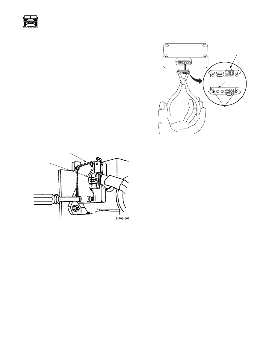
9.
Remove the calibrating resistor (Figure 3-17) from the
Fuel Solenoid Driver using special pliers (Klein D319B or
Stanadyne 30858).
CAUTION:
The Calibrating Resistor is specific to the injec-
tion pump. Do not damage the resistor. The calibrating resis-
tor identification number is located on the front of the
Calibrating Resistor (Figure 3-17).
CAUTION:
If the Calibrating Resistor is damaged or lost, the
Injection Pump must be removed for replacement or taken to a
Stanadyne dealer for calibration. If the Calibrating Resistor is
missing a DTC P1218 will set.
Figure 3-17: Calibrating Resister Transfer
Installation
1.
Install the calibrating resistor in the new Fuel Solenoid
Driver using the special pliers (Figure 3-17).
2.
Place the new heat transfer pad on the side of the Fuel
Solenoid Driver and insert the mounting screws through
the driver and the pad.
3.
Align the Fuel Solenoid Driver mounting screws with the
holes in the pump housing and tighten to 23 lb-in (2.75
N•m).
CAUTION:
Do not install the Fuel Solenoid Driver without
the heat transfer pad. Do not reuse a heat transfer pad. Use a
new heat transfer pad only. The heat transfer pad is required
to prevent overheating and rapid failure of the Fuel Solenoid
Driver.
CAUTION:
Do not overtighten the Fuel Solenoid Driver
mounting screws. Damage to the Fuel Solenoid Driver will re-
sult.
4.
Connect the Fuel Solenoid Driver wiring harness
connector.
5.
Loosen the upper Injection Pump retaining nut
approximately 1/2 turn (do not remove the nut).
6.
Rotate the Injection Pump back to it’s original position,
using the reference marks made previously and tighten the
Injection Pump retaining nuts.
7.
Install the intake manifold runner.
8.
Connect the upper radiator hose to the thermostat housing
and fill the coolant system.
9.
Perform the Injection Timing Adjustment Procedure
below.
FUEL
SOLENOID
DRIVER
WIRE
CONNECTOR
8-P03-002
ID NO.
4
REMOVAL
HOLES
INDEX
NOTCH

3-16
Fuel, Emissions, and Exhaust
___________________________________________
®
Injection Timing Stepper Motor
The stepper motor is used to advance or retard timing of the
electronic injection pump. The motor is controlled by the PCM
and is actuated by input signals primarily from the coolant, air,
and fuel temperature sensors.
A stepper motor fault will affect desired and measured injec-
tion timing degree readings on the scan tool. A difference of 5°
or more between the readings indicates a motor fault.
Stepper Motor Test
1.
Connect the scan tool to the diagnostic/data link connec-
tor.
2.
Start and run the engine until it reaches the normal
operating temperature.
3.
Note injection timing readings on the scan tool.
• If “desired” and “actual” injection timing readings differ
by 5° or more, continue the test.
• If readings are no more than 3°-4° apart, but a trouble
code was set, the problem is intermitent and probably
caused by a bad connection between the PCM and the
motor.
4.
Stop the engine and turn ignition to Off.
5.
Check the resistance between terminals A7 and A8 of the
brown 24 pin PCM harness connector (C29) for coil 1 low
(A8), and coil 1 high (A7) (Figure 3-19).
• If the resistance is between 10 and 50 ohms, continue
test.
• If the resistance is not within the specified range, the
problem is an open wire, a bad connection, or a failed
stepper motor.
6.
Check the resistance between terminals A9 and A10 of the
brown 24 pin PCM harness connector (C29) coil 2 low
(A9), and coil 2 high (A10) (Figure 3-19).
• If the resistance is 10-50 ohms, the problem is in the
PCM connection, or the PCM.
• If the resistance is other than specified, the problem is in
the wires to the PCM coil 2 terminals, a bad connection,
or the PCM has a fault.
Stepper Motor Replacement
Removal
1.
Disconnect the wire connector at the stepper motor.
2.
Remove the two torx screws retaining the stepper motor,
disconnect the actuator arm from the spring and remove
the stepper motor from the injection pump (Figure 3-18).
Figure 3-18: Stepper Motor Replacement
Installation
3.
Place the stepper motor on the injection pump while
aligning the notch in the actuating arm with the spring on
the pump.
4.
Install the two torx screws and torque to 40 lb-in (4.5
N•m).
5.
Connect the wire connection to the stepper motor.
Figure 3-19: Injection Timing Stepper Motor Circuit
STA
NA
DY
NE
STA
NAD
YNE
8-P03-001.4
STEPPER
MOTOR
INJECTION
PUMP
TORX
SCREWS
SPRING
ACTUATOR ARM
M
D
A
B
C
INJECTION TIMING
STEPPER MOTOR (ITS)
A3
A2
A6
A7
709 RED
708 T
A
N
710 ORG
71
1 YEL
C29
A8
A9
A10
A7
ITS
HI
ITS
LO
ITS
LO
ITS
HI
POWERTRAIN
CONTROL
MODULE
9-S03-003
MOTOR
HARNESS
CONNECTOR
A
B
C
D
LEGEND
Нет комментариевНе стесняйтесь поделиться с нами вашим ценным мнением.
Текст