Hummer H1 (2002+). Manual — part 69

____________________________________________
Transmission/Transfer Case 5-75
®
05745159
3
1.
Turn the ignition OFF.
2.
Disconnect the OSS Sensor connector from the
OSS Sensor.
3.
Connect a J– 39200 DVOM (covered in Electrical
Section 12) on AC Voltage scale between terminals
A and B at the OSS Sensor.
4.
Turn the ignition to the RUN position, and start the
engine.
5.
Place the transmission in D3 range.
6.
With the wheels rotating, slowly accelerate to 2000
engine RPM and hold.
Does the voltage drop or fluctuate at 2000 RPM?
—
Go to Step 17
Go to Step 4
4
1.
Turn the ignition OFF.
2.
Reconnect the OSS sensor harness to the sensor.
3.
Disconnect the VSS Buffer Module harness con-
nector from the component.
4.
Turn the ignition ON and turn the engine OFF.
5.
Set the J– 39200 DVOM on AC volts.
6.
Connect the J– 39200 DVOM between terminals 7
and 12 of the VSS Buffer Module harness connec-
tor.
7.
Start the engine.
8.
Place the transmission in D3 range.
9.
With the wheels rotating, slowly accelerate to 2000
engine RPM and hold steady.
Does the voltage drop or fluctuate at 2000 RPM?
Above 0.5 volts
AC
Go to Step 5
Go to Step 7
5
Inspect circuit 821 and circuit 822 for an intermittent
Did you find a problem?
__
Go to Step 12
Go to Step 6
6
Inspect circuit 821 and circuit 822 for an intermittent
short together or a short to ground.
Did you find a problem?
__
Go to Step 12
__
7
With the engine OFF, turn the ignition switch ON.
Select DC volts, and inspect for ignition voltage at ter-
minal 9 of the VSS Buffer Module harness.
Is the voltage greater than the specified value?
10.5 volts DC
Go to Step 9
Go to Step 8
8
Repair the intermittent open or high resistance in circuit
39.
Is the repair complete?
__
Go to Step 21
__
9
1.
Connect the J– 39200 DVOM between terminals 8
and 9 of the VSS Buffer Module harness connector.
Set the DVOM on DC volts.
2.
Turn the ignition to the Run position.
Is the voltage greater than the specified value?
10.5 volts DC
Go to Step 11
Go to Step 10
10
Repair the open or high resistance in circuit 451.
Is the repair complete?
__
Go to Step 21
__
DTC P0723 Output Speed Sensor Intermittent (Cont’d)
Step
Action
Value
Yes
No

5-76
Transmission/Transfer Case
_____________________________________________
®
11
1.
With the engine OFF, turn the ignition to the RUN
position.
2.
Using the J– 39200 DVOM, measure the voltage at
the VSS Buffer Harness connector terminal 13.
Is the voltage steady and within the specified voltage?
4.8-5.2 volts
DC
Go to Step 13
Go to Step 14
12
Repair the short in circuit 821 and circuit 822. Refer to
Electrical Diagnosis, Section 8.
Did you correct the problem?
__
Go to Step 21
__
13
1.
Turn the ignition to the OFF position.
2.
Reconnect the VSS Buffer Module harness to the
VSS Buffer Module.
3.
Set the J– 39200 DVOM on the DC volts scale.
4.
Back probe terminal 13 of the VSS Buffer Harness
connector with the
J– 39200 DVOM.
5.
Start the engine.
6.
Place the transmission in a D3 range.
7.
With the wheels rotating, slowly accelerate the
engine to 2000 RPM and hold.
Is the voltage reading steady within the specified value?
1.5-3.5 volts
DC
Go to Step 19
Go to Step 18
14
Is the voltage from step 11 greater than the specified
value?
5.2 volts DC
Go to Step 15
Go to Step 16
15
Inspect for a short to power in circuit 437.
Did you find a problem?
—
Go to Step 21
Go to Step 20
16
Inspect circuit 437 for continuity or short to ground.
Refer to Electrical Diagnosis, Section 8.
Did you find a problem?
—
Go to Step 21
Go to Step 19
17
Replace the OSS Sensor. Refer to 4L80-E On-Vehicle
Service Speed Sensor Replacement.
Is the replacement complete?
—
Go to Step 21
—
18
Replace the VSS Buffer Module.
Is the replacement complete?
—
Go to Step 21
—
19
Inspect the PCM terminals and connector for proper ten-
sion or corrosion.
Did you find a problem?
—
Go to Step 21
Go to Step 20
20
Replace the PCM. Refer to PCM Replacement/Pro-
gramming
, Section 6.
Is the replacement complete?
—
Go to Step 19
—
DTC P0723 Output Speed Sensor Intermittent (Cont’d)
Step
Action
Value
Yes
No

____________________________________________
Transmission/Transfer Case 5-77
®
05745159
21
In order to verify your repair, perform the fol-
lowing procedure:
1.
Select DTC.
2.
Select Clear Info.
3.
Operate the vehicle under the following conditions:
• Drive the vehicle in D3.
• The PCM must see a Transmission OSS greater
than 200 RPM and no change greater than 1000
RPM for 1 second.
4.
Select Specific DTC. Enter DTC P0723.
Has the test run and passed?
—
System OK
Begin the
Diagnosis
again. Go to
Step 1
DTC P0723 Output Speed Sensor Intermittent (Cont’d)
Step
Action
Value
Yes
No
5-78
Transmission/Transfer Case
_____________________________________________
®
DTC P0724 Brake Switch Circuit High Input
Circuit Description
The brake switch indicates brake pedal position. The normally-
closed brake switch supplies a B+ signal on circuit 810 to the
PCM. The signal voltage circuit is opened when the brakes are
applied. The PCM uses this signal to deenergize the converter
clutch solenoid when the brakes are applied.
This DTC detects a closed brake switch during decelerations.
Conditions For Setting DTC
• No DTC P0722, P0723.
• The PCM detects a closed brake switch/circuit (12
volts) for 2 seconds during decelerations and the follow-
ing events occur seven consecutive times: vehicle speed
is greater than 32 km/h (20 mph) for 6 seconds; then ve-
hicle speed is between 8 and 32 km/h (5 and 20 mph) for
4 seconds; then vehicle speed is less than 8 km/h (5
mph).
• All conditions exist with 7 occurrences.
Action Taken When The DTC Sets
• PCM disregards the brake switch state if TPS is greater
than 12% and vehicle speed is greater than 45 mph.
• The PCM will NOT illuminate the warning lamp.
Conditions For Clearing The DTC
• The DTC can be cleared using a scan tool. The DTC
will be cleared when the vehicle has achieved 40 warm-
up cycles without a failure reported.
• The PCM will cancel the DTC default actions when the
fault no longer exists and the ignition is cycled “off”
long enough to power down the PCM.
Diagnostic Aids
• Inspect the wiring for poor electrical connections at the
PCM and brake switch. Look for bent, backed out, de-
formed or damaged terminals. Check for weak terminal
tension as well. Also check for a chafed wire that could
short to bare metal or other wiring. Inspect for a broken
wire inside the insulation.
• When diagnosing for a possible intermittent short or
open condition, move the wiring harness while observ-
ing test equipment for a change.
• Check customer driving habits and/or unusual traffic
conditions (i.e. stop and go, expressway).
• Check brake switch for proper mounting and adjust-
ment.
• If any engine DTCs or TPS codes are present diagnose
and clear these DTCs first. Then check to see if the
transmission DTCs have reset.
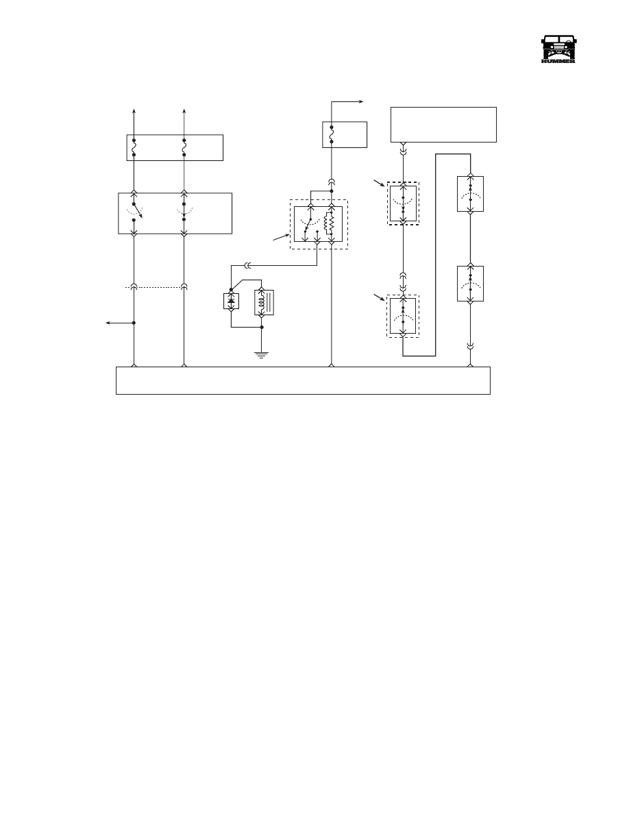
FUSE 4D
15 AMP
INTERIOR
FUSE 6B
5 AMP
INTERIOR
HOT AT
ALL TIMES
HOT IN RUN
AND START
STOP LAMP
SWITCH
TCC CRUISE
BRAKE SWITCH
A
D
B
C
TO
STOP
LAMPS
C1
31
40
10 OR
291 PK
22 RD
810 PP
STOP
LAMP
SIGNAL
TCC/ CRUISE
BRAKE SIGNAL
FUSE 2C
10 AMP
INTERIOR
HOT IN RUN
AND START
C1-1
30
85
87
86
A/C COMPRESSOR
ENABLE
RELAY CONTROL
A/C
COMPRESSOR
CLUTCH
DIODE
C5-8
400 LG
A/C COMPRESSOR
CLUTCH RELAY
EXTERIOR
FUSE
BOX
G1
440 RD
59 BK
348 BR
C28-D5
HVAC
CONTROL
MODULE
C6-J8
H
347 YL
A/C
REQUEST
SIGNAL
TEMPERATURE
CUTOUT
SWITCH
HVAC
UNIT
C1-39
C4-2
198 TN
C4-5
438 OR
439 YL
C27-C2
A/C
REQUEST
SIGNAL
COMPRESSOR
HIGH
PRESSURE
CUTOUT
SWITCH
AMBIENT
TEMP
CUTOUT
SWITCH
LOW
PRESSURE
CUTOUT
SWITCH
9-S12-054
Нет комментариевНе стесняйтесь поделиться с нами вашим ценным мнением.
Текст