Hummer H1 (2002+). Manual — part 293
____________________________________________________
PCM/Tech 1 Scan Tool 105
®
05745159
DTC P1216 - Fuel Solenoid Response Time Too Short
Step
Action
Value(s)
Yes
No
1
Important:
Before clearing DTC(s) use the scan tool “Capture Info” to
record freeze frame and failure records for reference, as data will be lost
when “Clear Info” function is used.
Was the “On-Board Diagnostic (OBD) System Check” performed?
—
Go to Step 2.
Go to OBD
System Check.
2
Is DTC P0219 set?
—
Go to
applicable
table.
Go to Step 3.
3
Will engine start?
—
Go to Step 4.
Go to Step 7.
4
1. Engine at operating temperature.
2. Observe Inj. Pump Closure Time on scan tool.
Is the scan tool display less than the specified value?
0.75 ms
Go to Step 5.
Go to Step 6.
5
1. Engine running.
2. Again, observe Inj. Pump Closure Time on scan tool.
Does Inj. Pump Closure Time display the specified value?
0.1 ms
Go to Step 8.
Go to Step 10.
6
DTC is intermittent. If no additional DTCs are stored, refer to “Diagnostic
Aids”. If additional DTCs are stored, refer to those charts(s) first.
Are additional DTCs stored?
—
Go to
applicable
DTC table.
Go to
Diagnostic Aids
7
1. Check the Closure ground circuit for an open.
2. If the Closure circuit is open, repair as necessary.
Was a repair performed?
—
Go to Step 12. Go to Step 10.
8
1. Check the Closure signal circuit for an open or short to ground.
2. If the Closure signal circuit is open or shorted to ground, repair as neces-
sary.
Was a repair performed?
—
Go to Step 12.
Go to Step 9.
9
Check the Closure signal circuit for a poor connection at PCM and replace
terminal if necessary.
Is action complete?
—
Go to Step 12. Go to Step 11.
10
Replace injection pump. Notice: If injection pump is faulty, the new injec-
tion pump must be timed. Refer to Checking and Adjusting Injection Timing
in Section 4.
Is the action complete?
—
Go to Step 12.
—
11
Replace the faulty PCM. Notice: If the PCM is faulty, the new PCM must
be programmed. Go to PCM replacement and programming procedures.
Is the action complete?
—
Go to Step 12.
—
12
1. Using the Scan Tool, select “DTC”, “Clear Info”.
2. Start engine and idle at normal operating temperature.
3. Select “DTC”, “Specific”, then enter the DTC number which was set.
4. Operate vehicle within the conditions for setting this DTC as specified in
the supporting text.
Does the Scan Tool indicate that this diagnostic Ran and Passed?
—
Go to Step 13.
Go to Step 2.
13
Using the Scan Tool, select “Capture Info”, “Review Info”.
Are any DTCs displayed that have not been diagnosed?
—
Go to the
applicable
DTC table
System OK.
106
PCM/Tech 1 Scan Tool
___________________________________________________
®
DTC P1217 Fuel Solenoid Response Time Too
Long
Circuit Description
The injection pump delivers fuel to individual cylinders by
opening and closing a solenoid control fuel valve. The PCM
monitors the amount of time it takes for the fuel solenoid valve
to physically close after commanded to close. Closure time out
of range is seen as a fault. This response time is measured in
milliseconds. This is a type D DTC.
Conditions for Setting the DTC
• Battery voltage greater than 10 volts and less than 16
volts.
• Engine coolant temperature greater than -1°C (34°F).
• Engine speed greater than 506 RPM.
• Requested fuel rate is greater than 0.0 mm.
• Inj. Pump Closure Time less than .75 ms.
Action Taken When the DTC Sets
Possible poor performance.
Conditions for Clearing the MIL/DTC
• A History DTC will clear when forty consecutive
warm-up cycles that the diagnostic does not fail (coolant
temperature has risen 5°C (40°F) from start up coolant
temperature and engine coolant temperature exceeds
71°C (160°F) that same ignition cycle).
• Use of a scan.
Diagnostic Aids
A weak (mechanical failure) fuel solenoid will result in a DTC
P1217. If DTC P1217 is set with any other DTCs, diagnose
them first. If the vehicle is running close to the DTC setting
closure time, vehicle should be checked during cold start ups
and during hot conditions.
Test Description
Number(s) below refer to the number(s) on the diagnostic ta-
ble.
3. This step will determine if DTC P1217 is a hard failure or an
intermittent.
This step will determine if the solenoid is at fault, or if there is
a problem with the PCM or wiring.
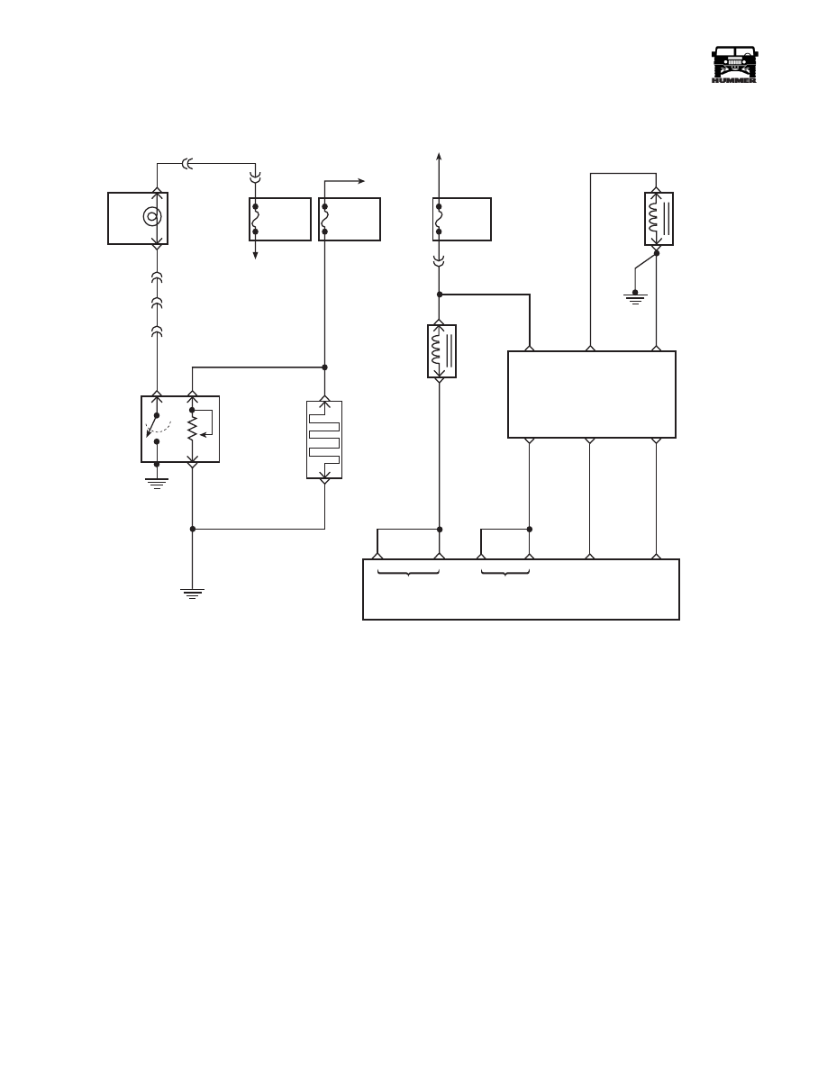
FUSE 3B
20AMP
EXTERIOR
FUSE BOX
DRAIN
FILTER
HOT IN RUN
AND START
WATER IN
FUEL LIGHT
LEFT HAND
STATUS CENTER
C9-D
C3-F4
C1-45
B
A
327 YL
C
C9-J
WATER IN
FUEL
SENSOR
FUEL
HEATER
291 PK
57 BK
G2
57 BK
C
A
9-S12-056
FUSE 4B
5AMP
INTERIOR
FUSE BOX
TO
IGNITION
SWITCH
C3-N7
30 GY
FUSE 3A
20AMP
EXTERIOR
FUSE BOX
HOT IN RUN
AND START
C5-A4
239 PK
ENGINE
SHUTOFF
SOLENOID
FUEL
SOLENOID
701 DB
A
A
A
B
C
D
F
E
A
B
FUEL
SOLENOID
DRIVER
IGN
FUEL
SOLENOID
HIGH
FUEL
SOLENOID
LOW
FUEL
SOLENOID
CONTROL
CLOSURE
SIGNAL
CLOSURE
GROUND
ESO
SOLENOID
CONTROL
FUEL INJECT
CONTROL
CLOSURE
SIGNAL
CLOSURE
GROUND
712 LG
713 RD
491 BK
POWER
CONTROL
MODULE
C28-C15
C28-D3
C28-C3
C27-C13
C29-A1

____________________________________________________
PCM/Tech 1 Scan Tool 107
®
05745159
DTC P1217 - Fuel Solenoid Response Time Too Long
Step
Action
Value(s)
Yes
No
1
Important:
Before clearing DTC(s) use the scan tool “Capture Info” to
record freeze frame and failure records for reference, as data will be lost
when “Clear Info” function is used.
Was the “On-Board Diagnostic (OBD) System Check” performed?
—
Go to Step 2.
Go to OBD
System Check.
2
Is DTC P0370 set?
—
Refer to
applicable
table.
Go to Step 3.
3
1. Engine at operating temperature.
2. Observe Inj. Pump Closure Time on scan tool.
Is the scan tool display greater than or equal to the specified value?
2.4 ms
Go to Step 5.
Go to Step 4.
4
1. All accessories on (includes aftermarket add-ons).
2. Engine idling.
3. All post glow plug cycles completed.
4. With a J–39200 connected to ground, measure voltage at the FUEL SOL
fuse (fuel solenoid driver ignition feed circuit) in the U/H relay center.
Is voltage between specified value?
12 - 15v
Go to Step 7.
Go to Step 6.
5
DTC is intermittent. If no additional DTCs are stored, refer to “Diagnostic
Aids”. If additional DTCs are stored, refer to those charts(s) first.
Are additional DTCs stored?
—
Go to
applicable
DTC table.
Go to
Diagnostic Aids
6
Repair the fuel solenoid driver ignition feed circuit poor connections or
aftermarket add-ons.
Was a repair performed?
—
Go to Step 8.
—
7
Replace injection pump. Notice: If injection pump is faulty, the new injec-
tion pump must be timed. Refer to Checking and Adjusting Injection Timing
in Section 4.
Is the action complete?
—
Go to Step 8.
—
8
1. Using the Scan Tool, select “DTC”, “Clear Info”.
2. Start engine and idle at normal operating temperature.
3. Select “DTC”, “Specific”, then enter the DTC number which was set.
4. Operate vehicle within the conditions for setting this DTC as specified in
the supporting text.
Does the Scan Tool indicate that this diagnostic Ran and Passed?
—
Go to Step 9.
Go to Step 2.
9
Using the Scan Tool, select “Capture Info”, “Review Info”.
Are any DTCs displayed that have not been diagnosed?
—
Go to the
applicable
DTC table
System OK.
108
PCM/Tech 1 Scan Tool
___________________________________________________
®
DTC P1218 Injection Pump Calibration
Circuit
Circuit Description
The PCM uses a calibrated resistor mounted internally in the
injection pump to determine fuel rates. The resistor value is
stored in the PCM memory. If the PCM memory has been dis-
turbed or the PCM has been replaced, the PCM will relearn the
resistor value on the next ignition cycle. This is a type B DTC.
Conditions for Setting the DTC
• PCM currently does not have a valid resistor valve.
• PCM is unable to read a resistor value.
Action Taken When the DTC Sets
The lowest fuel table. Possible poor performance problem.
Conditions for Clearing the MIL/DTC
• The PCM will turn the MIL off after three consecutive
trips without a fault condition.
• A History DTC will clear when forty consecutive
warm-up cycles that the diagnostic does not fail (coolant
temperature has risen 5°C (40°F) from start up coolant
temperature and engine coolant temperature exceeds
71°C (160°F) that same ignition cycle).
• Use of a scan.
Diagnostic Aids
Check connection at fuel injector driver. Clear DTC, and cycle
ignition. If DTC clears, treat condition as intermittent.
Test Description
Number(s) below refer to the number(s) on the diagnostic ta-
ble.
3. This step will determine if there is a problem with the con-
nection at the fuel solenoid driver or faulty injection pump.
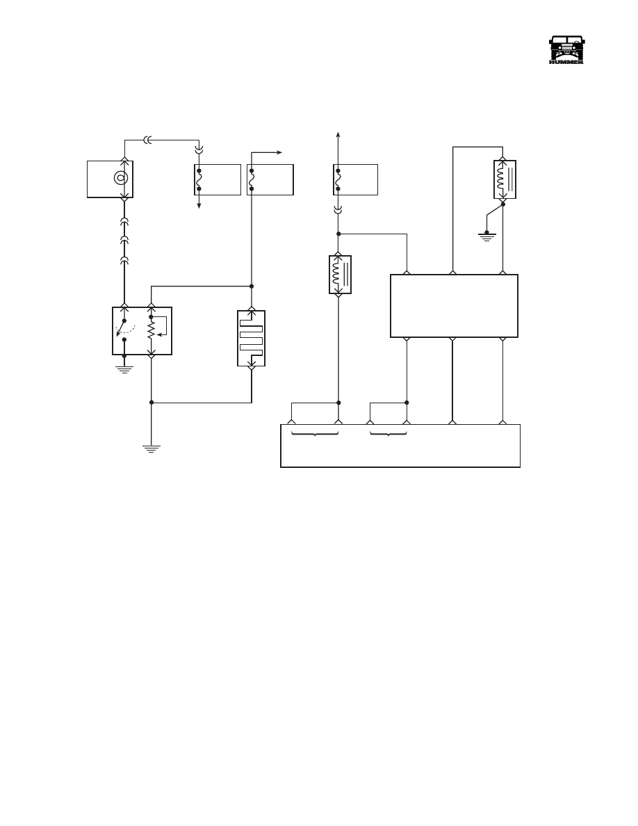
FUSE 3B
20AMP
EXTERIOR
FUSE BOX
DRAIN
FILTER
HOT IN RUN
AND START
WATER IN
FUEL LIGHT
LEFT HAND
STATUS CENTER
C9-D
C3-F4
C1-45
B
A
327 YL
C
C9-J
WATER IN
FUEL
SENSOR
FUEL
HEATER
291 PK
57 BK
G2
57 BK
C
A
9-S12-056
FUSE 4B
5AMP
INTERIOR
FUSE BOX
TO
IGNITION
SWITCH
C3-N7
30 GY
FUSE 3A
20AMP
EXTERIOR
FUSE BOX
HOT IN RUN
AND START
C5-A4
239 PK
ENGINE
SHUTOFF
SOLENOID
FUEL
SOLENOID
701 DB
A
A
A
B
C
D
F
E
A
B
FUEL
SOLENOID
DRIVER
IGN
FUEL
SOLENOID
HIGH
FUEL
SOLENOID
LOW
FUEL
SOLENOID
CONTROL
CLOSURE
SIGNAL
CLOSURE
GROUND
ESO
SOLENOID
CONTROL
FUEL INJECT
CONTROL
CLOSURE
SIGNAL
CLOSURE
GROUND
712 LG
713 RD
491 BK
POWER
CONTROL
MODULE
C28-C15
C28-D3
C28-C3
C27-C13
C29-A1
Нет комментариевНе стесняйтесь поделиться с нами вашим ценным мнением.
Текст