Hummer H1 (2002+). Manual — part 31
____________________________________________________________________
Engine 2-85
®
05745159
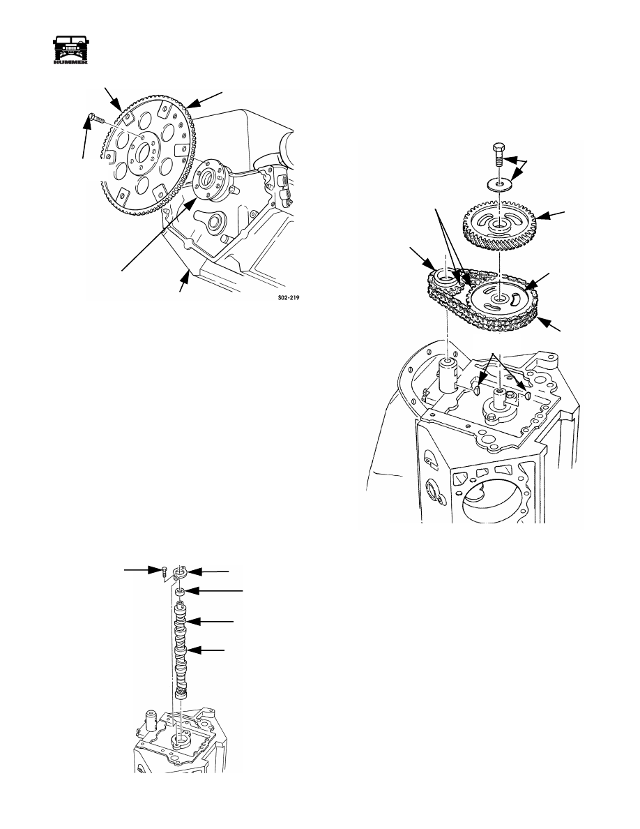
Figure 2-165: Flywheel Installation
CAMSHAFT INSTALLATION
1.
Place engine in upright position so cam bearing bores are
vertical.
2.
Lubricate camshaft bearing journals with engine oil. Then
lubricate cam bearings with long nozzle oil can.
3.
Lubricate camshaft lobes with assembly lube.
4.
Install 8-10 in. (20 -25 cm) long bolt or threaded rod on
cam sprocket bolt hole. Bolt will serve as handle and make
cam installation easier.
5.
Install camshaft. Lower and guide cam carefully through
and into bearings (Figure 2-166).
6.
Lubricate and install camshaft spacer and thrust plate.
Beveled edge of spacer faces toward cam.
7.
Apply 1-2 drops Loctite 242 to thrust plate bolt threads.
Then install and tighten bolts 17 lb-ft (23 N•m) torque.
8.
Remove bolt or rod from camshaft.
Figure 2-166: Camshaft Installation
TIMING CHAIN-SPROCKET-GEAR INSTALLATION
1.
Rotate crankshaft so #1 piston is at TDC.
2.
Install sprocket drive keys in camshaft and crankshaft
(Figure 2-167).
Figure 2-167: Timing Chain - Sprocket -
Gear Installation
3.
Place block in upright position so cam is facing up. Then
rotate camshaft so drive key is toward top of block.
4.
Assemble timing chain and sprockets. Make sure sprocket
timing marks are aligned as shown (Figure 2-167).
5.
Align sprockets with drive keys in crankshaft and
camshaft. Then install chain and sprockets as assembly
(Figure
2-167). Turn camshaft to align sprockets if
necessary. Do not turn sprockets.
6.
Check chain deflection with dial indicator. If deflection is
greater than 0.51 in. (13 mm), chain is stretched and will
have to be replaced.
7.
Install injection pump drive gear, thrust washer, flat
washer (if equipped), and bolt (Figure 2-167). Tighten bolt
to 126 lb-ft (171 N•m) torque. Apply 1-2 drops Loctite
242 to bolt threads before installation. Position gear so
timing marks is at 12 o’clock position.
8.
Lubricate chain, sprockets, and gear with engine oil.
CONVERTER BOLT PADS
FLYWHEEL
CRANKSHAFT
FLANGE
CYLINDER BLOCK
FLYWHEEL
BOLTS (6)
BOLTS (2)
THRUST PLATE
SPACER
CAM LOBES
CAM JOURNALS
6-S02-075
CRANKSHAFT
SPROCKET
TIMING MARK
LOCATIONS
THRUST WASHER
AND BOLT
INJECTION
PUMP
DRIVE
GEAR
CAMSHAFT
SPROCKET
TIMING
CHAIN
SPROCKET
DRIVE KEYS
6-S02-075

2-86
Engine
_____________________________________________________________________
®
FRONT COVER AND BAFFLE INSTALLATION
1.
Install new seal in front cover with installer tool J–22102.
2.
Apply sealer to front cover as follows:
• Use anaerobic sealer such as Loctite 510 on cover sur-
faces that contact block (Figure 2-168).
• Use RTV-type sealer such as Permatex High Temp, Ul-
tra Blue, or Loctite 599 (gray) to oil pan contact surface
of cover (Figure 2-168).
3.
Install front cover on engine block (Figure 2-168). Be sure
cover is seated on dowels, block face, and oil pan.
4.
Install and tighten front cover bolts as follows:
• Tighten cover-to-engine block bolts to 33 lb-ft (45 N•m)
• Tighten cover-to-oil pan bolts to 4-10 lb-ft (5-14 N•m)
5.
Install baffle on front cover. Maintain minimum clearance
of 0.040 in. (1.02 mm) between baffle and injection pump
gear. Tighten baffle attaching bolts/nuts to 33 lb-ft (45
N•m) torque.
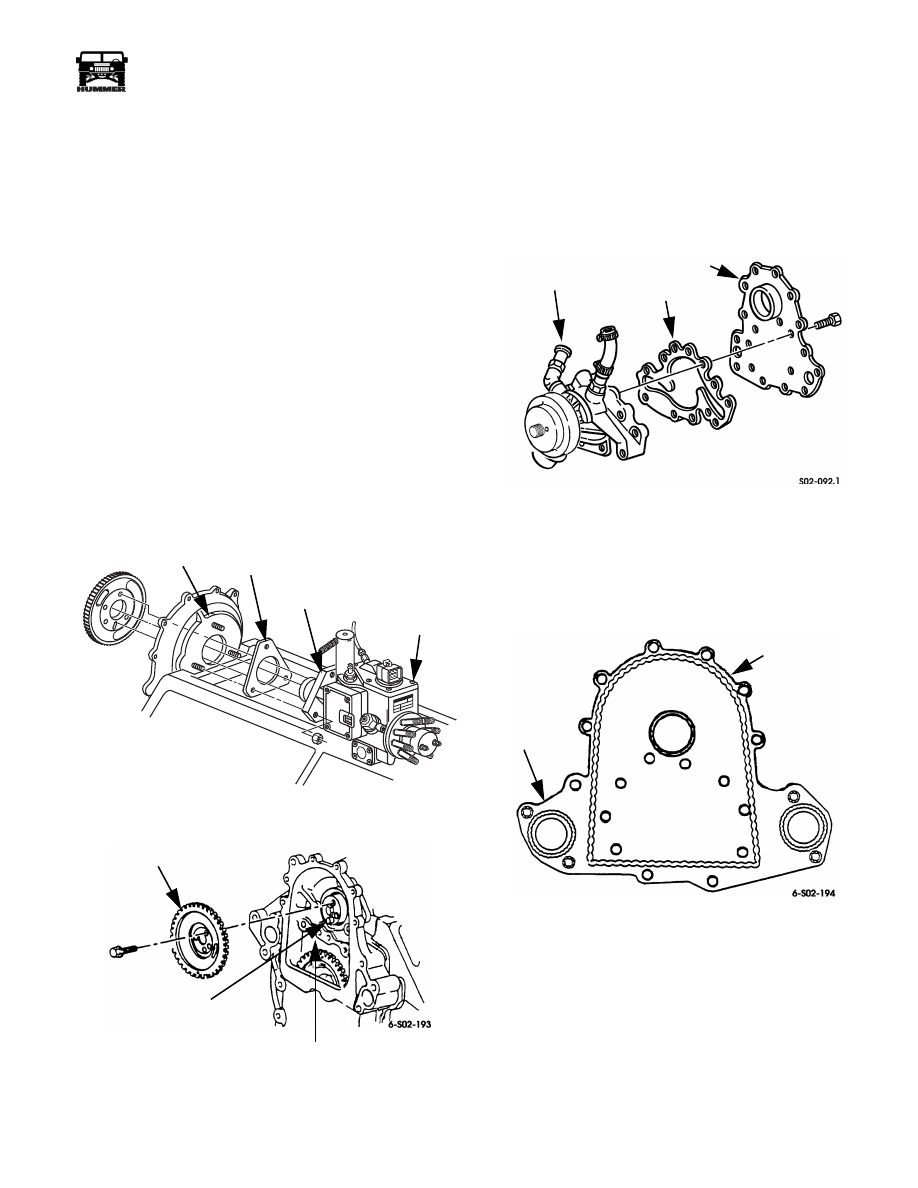
Figure 2-168: Front Cover Installation
SEALANT
DIAGRAM
BAFFLE
FRONT COVER
SEAL
RTV SEALANT
APPLICATION
ANAEROBIC
SEALER
HERE
HERE
RTV SEALANT
HERE
____________________________________________________________________
Engine 2-87
®
05745159
FUEL INJECTION PUMP INSTALLATION
1.
Install injection pump gasket on front cover studs.
2.
Mount injection pump on front cover studs (Figure 2-169).
Install retaining nuts finger tighten.
3.
Rotate crankshaft if necessary, to place timing mark on
injection pump drive gear at 12 o’clock position.
4.
Install pump driven gear into fron cover so the timing
mark on the driven gear aligns with the timing mark on the
drive gear.
5.
Turn pump shaft (not gear), until shaft pin aligns with slot
in driven gear. Then slide pump into place and secure it
with gear attaching bolts. Apply 1-2 drops Loctite 242 to
bolt threads beforehand and tighten bolts to 13-20 lb-ft
(18-27 N•m) torque. Tighten pump retaining nuts to 31 lb-
ft (42 N•m) torque.
6.
Perform Timing Setting Procedure to adjust injection
pump timing. Pump may also require TDC offset
adjustment if front cover was replaced, or PCM was
replaced with the fuel injection pump.
Figure 2-169: Injection Pump Installation
Figure 2-170: Pump Driven Gear Installation
WATER PUMP AND ADAPTER PLATE
INSTALLATION
1.
Apply Permatex #2 to both sides of gasket and install gas-
ket and water pump on adapter plate (Figure 2-171).
Tighten adapter plate bolts to 13-20 lb-ft (18-27 N•m).
Figure 2-171: Assembling Water Pump and Adapter
Plate
2.
Apply Loctite gasket maker or 510 to contact area of
adapter plate as shown (Figure 2-172).
Figure 2-172: Adapter Plate Sealer Application
3.
Install adapter plate and water pump on front cover.
Tighten all studs and short bolts marked A to 13-20 lb-ft
(18-27 N•m). Tighten large studs and large bolt marked B
to 25-37 lb -ft (34-50 N•m) (Figure 2-173).
6-S02-050.1
FRONT COVER
TIMING MARK
PUMP
GASKET
PUMP
TIMING MARK
INJECTION
PUMP
DRIVE GEAR
DRIVEN GEAR
CAMSHAFT
PIN
WATER PUMP
GASKET
ADAPTER PLATE
SEALER
ADAPTER
BEAD
PLATE
2-88
Engine
_____________________________________________________________________
®
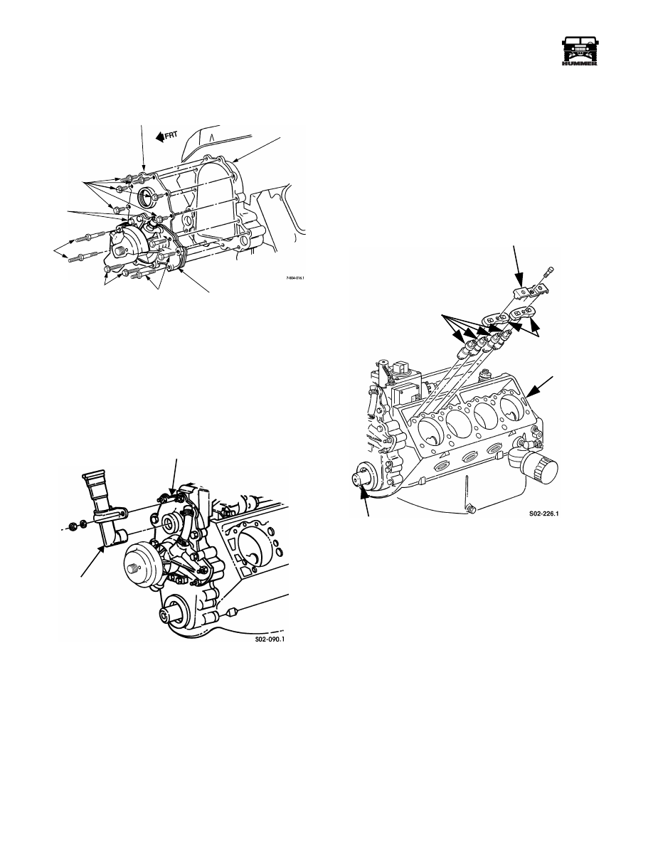
Figure 2-173: Adapter Plate and Water Pump
Installation
4.
Install oil fill tube on adapter plate with two washers and
nuts. Tighten nuts to 13-20 lb-ft (18-27 N•m)
(Figure 2-174).
5.
Install pulley on water pump shaft flange.
Figure 2-174: Oil Fill Tube Installation
VALVE LIFTER INSTALLATION
1.
Prime valve lifters in kerosene then engine oil. Immerse
lifter in kerosene first and oil last. Then pump plunger with
pushrod to force solution through lifter.
2.
Lubricate lifters with oil and install in cylinder block.
3.
Position guide plates on lifters. Then install guide clamps
and bolts. Tighten bolts to 15-20 lb-ft (20 -27 N•m)
(Figure 2-175).
4.
Rotate crankshaft several turns to ensure lifters move
freely.
Figure 2-175: Valve Lifter Installation
ADAPTER PLATE
FRONT
COVER
WATER PUMP
A
A
B
B
A
OIL FILL TUBE
ADAPTER PLATE
GUIDE CLAMP
VALVE LIFTERS
GUIDE PLATES
BLOCK
CRANKSHAFT
Нет комментариевНе стесняйтесь поделиться с нами вашим ценным мнением.
Текст