Hummer H1 (2002+). Manual — part 247
_____________________________________________________
Electrical System 12-209
®
05745159
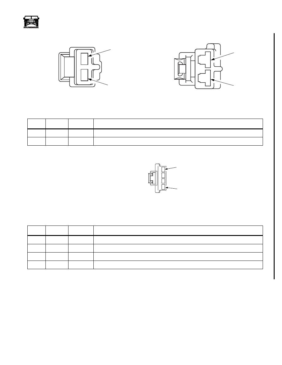
2 WAY REAR WINDOW DEFROSTER HARNESS LOCATION: C-PILLAR INTERMEDIATE
4 WAY REAR WINDOW DEFROSTER SWITCH CONNECTOR LOCATION: BACK OF THE HVAC
PIN
CKT
COLOR
DESCRIPTION
A
58
BK
Ground for the rear window defroster G4
B
689
PK
Rear window defroster 12 volt supply
PIN
CKT
COLOR
DESCRIPTION
A
688
RD
Fused battery voltage to the rear window defroster switch
B
399
DG
Fused ignition voltage to the rear window defroster switch
C
59
BK
Ground G4
D
689
PK
Rear window defroster 12 volt supply
9-S12-105
9-S12-106
C45 FEMALE
C45 MALE
A
A
B
B
9-S12-158
C46 FEMALE
A
D
4-1-00
12-210
Electrical System
______________________________________________________
®
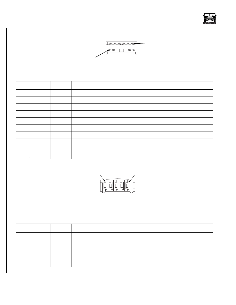
10 WAY CARGO DOOR LOCK DELAY MODULE CONNECTOR LOCATION: ON MODULE
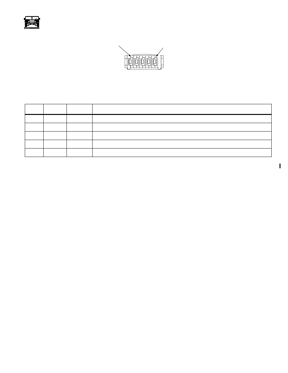
5 WAY DRIVERS DOOR LOCK SWITCH CONNECTOR LOCATION: IN THE DRIVERS DOOR
PIN
CKT
COLOR
DESCRIPTION
1
Empty
2
Empty
3
59
BK
Ground G4
4
Empty
5
118
BR
Lock signal to the cargo door lock delay module
6
117
PK
Unlock signal to the cargo door lock delay module
7
Empty
8
Empty
9
517
OR
Fused battery input to the cargo door lock delay module
10
121
YL
Lock signal to the cargo door lock actuator
PIN
CKT
COLOR
DESCRIPTION
1
120
LG
Oscillating power/ground circuit
2
56
BK
Ground G4
3
517
OR
Fused battery input to the drivers door lock actuator
4
56
BK
Ground G4
5
119
TN
Oscillating power/ground circuit.
00-S12-022
C47 FEMALE
10
1
00-S12-021
C48 FEMALE
1
5
4-1-00
_____________________________________________________
Electrical System 12-211
®
05745159
5 WAY PASSENGER DOOR LOCK SWITCH CONNECTOR LOCATION: IN THE PASSENGERS DOOR
PIN
CKT
COLOR
DESCRIPTION
1
122
PP
Lock signal from the switch to the module
2
120
LG
Oscillating power/ground circuit
3
517
OR
Fused battery input to the passenger door lock switch
4
119
TN
Oscillating power/ground circuit
5
121
YL
Unlock signal from the switch to the module
00-S12-021
1
5
C49 FEMALE
3-1-01
12-212
Electrical System
______________________________________________________
®
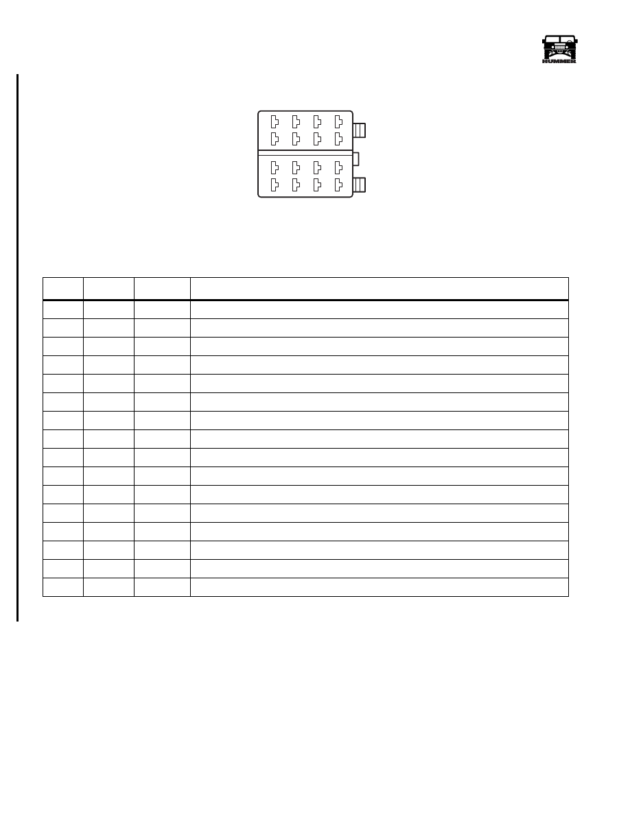
16 WAY RADIO HARNESS LOCATION: BACK OF THE RADIO
PIN
CKT
COLORS
DESCRIPTION
1
Empty
2
Empty
3
14
LB
Radio illumination
4
137
RD
Fused battery input to the radio (Ignition)
5
6
17
PP
Dimmer Circuit
7
476
GY
Fused radio memory feed (Battery)
8
59
BK
Ground G4
9
818
PP
Right rear speaker signal (Positive)
10
819
BK
Right rear speaker signal (Negative)
11
805
GY
Right front speaker signal (Positive)
12
811
BK
Right front speaker signal (Negative)
13
804
WH
Left front speaker signal (Positive)
14
813
BK
Left front speaker signal (Negative)
15
820
DG
Left rear speaker signal (Positive)
16
821
BK
Left rear speaker signal (Negative)2
00-S12-004
9
10
11
12
13
14
15
16
1
2
3
4
5
6
7
8
C56 FEMALE
3-1-01
Нет комментариевНе стесняйтесь поделиться с нами вашим ценным мнением.
Текст