Hummer H1 (2002+). Manual — part 35
________________________________________________________________________________
3-1
®
5745159
Section 3 Fuel, Emissions, and Exhaust
TABLE OF CONTENTS
Air Cleaner Filter Element Service . . . . . . . . . . . . . . . . . . .3-21
Air Cleaner Service . . . . . . . . . . . . . . . . . . . . . . . . . . . . . . . . . . .3-19
Air Horn . . . . . . . . . . . . . . . . . . . . . . . . . . . . . . . . . . . . . . . . . . . .3-21
Air Induction Hose Replacement . . . . . . . . . . . . . . . . . . . .3-22
Air Intake Vent Line Replacement . . . . . . . . . . . . . . . . . . . . . . .3-23
Diesel Fuel Injection System . . . . . . . . . . . . . . . . . . . . . . . . . . .3-36
Drainage Bracket Replacement . . . . . . . . . . . . . . . . . . . . . . . . .3-23
Engine Temperature Sender Replacement . . . . . . . . . . . . . . . .3-40
Exhaust System
Catalytic Converter Replacement. . . . . . . . . . . . . . . . . . . .3-44
Crossover Pipe Replacement . . . . . . . . . . . . . . . . . . . . . . .3-44
Muffler Replacement . . . . . . . . . . . . . . . . . . . . . . . . . . . . . .3-42
Drain Hose and Valve Replacement. . . . . . . . . . . . . . . . . .3-32
Service . . . . . . . . . . . . . . . . . . . . . . . . . . . . . . . . . . . . . . . . .3-31
Fuel Injection Pump Boot Replacement . . . . . . . . . . . . . . . . . .3-33
Fuel Injection System
Injection Line Bracket and Clamp . . . . . . . . . . . . . . . . . . .3-36
Fuel Lift Pump Service . . . . . . . . . . . . . . . . . . . . . . . . . . . . . . . .3-33
Fuel System
Contamination . . . . . . . . . . . . . . . . . . . . . . . . . . . . . . . . . . .3-41
Diagnosis . . . . . . . . . . . . . . . . . . . . . . . . . . . . . . . . . . . . . . . .3-6
Electronic Accelerator Pedal . . . . . . . . . . . . . . . . . . . . . . . .3-4
Electronic Injection Pump. . . . . . . . . . . . . . . . . . . . . . . . . . .3-3
Essential Tools. . . . . . . . . . . . . . . . . . . . . . . . . . . . . . . . . . .3-45
Fuel Filter-Water Separator . . . . . . . . . . . . . . . . . . . . . . . . . 3-3
Fuel Injectors . . . . . . . . . . . . . . . . . . . . . . . . . . . . . . . . . . . . . 3-4
Fuel Lift Pump . . . . . . . . . . . . . . . . . . . . . . . . . . . . . . . . . . . . 3-2
Fuel Selector Valve . . . . . . . . . . . . . . . . . . . . . . . . . . . . . . . 3-30
Fuel Tanks, Lines, and Valves . . . . . . . . . . . . . . . . . . . . . . . 3-4
Glow Plugs. . . . . . . . . . . . . . . . . . . . . . . . . . . . . . . . . . . . . . . 3-4
Auxiliary Fuel Tank . . . . . . . . . . . . . . . . . . . . . . . . . . . . . . . 3-26
Draining . . . . . . . . . . . . . . . . . . . . . . . . . . . . . . . . . . . . . . . . 3-22
Fuel Level Transmitter and Tank Access
Plate Service . . . . . . . . . . . . . . . . . . . . . . . . . . . . . . . . . . . 3-28
Fuel Tank Vent Line Service. . . . . . . . . . . . . . . . . . . . . . . . 3-29
Main Fuel Tank . . . . . . . . . . . . . . . . . . . . . . . . . . . . . . . . . . 3-24
Main/Auxiliary Tank Fuel Line . . . . . . . . . . . . . . . . . . . . . . 3-29
Vent Filter Replacement . . . . . . . . . . . . . . . . . . . . . . . . . . 3-29
Relay/Controller Replacement . . . . . . . . . . . . . . . . . . . . . 3-40
Service . . . . . . . . . . . . . . . . . . . . . . . . . . . . . . . . . . . . . . . . . 3-35
Powertrain Control Module . . . . . . . . . . . . . . . . . . . . . . . . . . . . . 3-6
Scan Tool Diagnosis. . . . . . . . . . . . . . . . . . . . . . . . . . . . . . . . . . 3-11
Sensor and Switch Service . . . . . . . . . . . . . . . . . . . . . . . . . . . . 3-40
Sensor, Oil Pressure Switch, and Transmitter . . . . . . . . . . . . . 3-40
Weathercap Replacement . . . . . . . . . . . . . . . . . . . . . . . . . . . . . 3-22
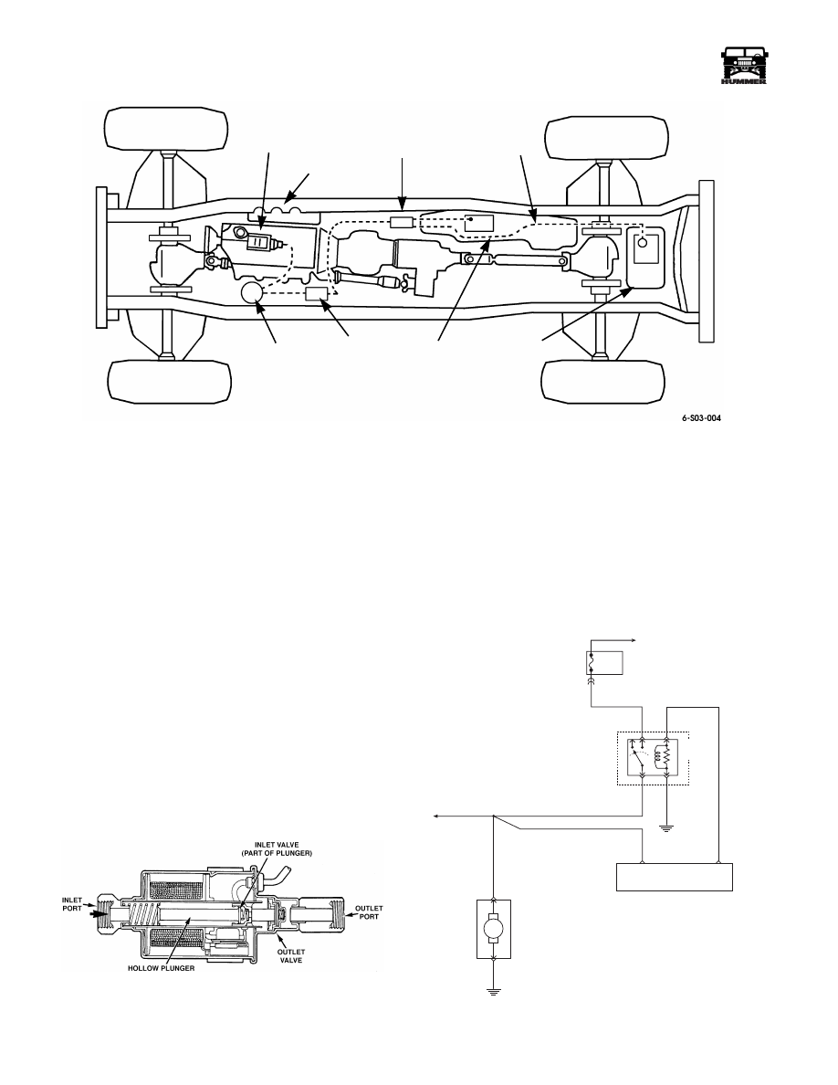
FUEL SYSTEM
The fuel system components include:
• A 25 gallon (94.6 liter) fuel tank
• Fuel tank supply and return lines
• An electric fuel-lift pump
• A fuel filter-water separator assembly
• A gear driven fuel injection pump
• Individual fuel injector nozzles for each cylinder
• Fuel line check valves on the filtered side of the fuel
system
• Fuel level transmitter (in fuel tank)
• Fuel drain back lines (at pump and injectors)
• A 17 gallon (64.3 liter) auxiliary fuel tank and selector
switch
• Glow plugs (all cylinders)
The fuel supply and return lines are attached with quick con-
nect fittings.
3-2
Fuel, Emissions, and Exhaust
_____________________________________________
®
Figure 3-1: Fuel Supply System
Fuel Lift Pump
The fuel lift pump is located on the firewall near the drivers
side of the engine. The electric fuel lift pump has a hollow
plunger that slides in a bore located in the center passage be-
tween the inlet and outlet ports (Figure 3-2). An inlet valve is
mounted on one end of the hollow plunger, and an outlet valve
is positioned at the outlet end of the center passage. Both
valves are closed by spring force.
The lift pump is designed to move fuel under a low (suction)
pressure from the fuel tank and deliver it through the filter to
the transfer pump, inside the fuel injection pump. To operate
correctly, the injection pump must have fuel at the correct pres-
sure and without air bubbles.
The lift pump is checked as part of the fuel supply system diag-
nosis. The lift pump should deliver fuel with a minimum vol-
ume of one half pint (0.24 liter) in 15 seconds and tee'd in at
the injection pump fuel inlet connection running at idle, with a
pressure of 5.8 to 8.7 psi (40 to 60 kPa). The lift pump suction
line from the fuel tank must be air tight for correct operation of
the injection pump.
Any air present in the fuel system will
cause runability problems and possible diagnostic trouble
codes (DTCs) to be set in PCM memory.
Figure 3-2: Fuel Lift Pump Construction
The electrical circuit for the lift pump involves several main
components (Figure 3-3). A relay mounted in the exterior fuse
box, and the lift pump itself, mounted near the filter on the left
side of the engine compartment.
When the driver moves the ignition switch to the “RUN” posi-
tion, the lift pump relay is energized by the PCM for 5 to 20
sec., depending on PCM time out.
As soon as the PCM receives RPM signals from the EFI pump
the relay is energized again. The lift pump remains running as
long as the engine runs.
Figure 3-3: Fuel Lift Pump Electrical Circuit
FUEL
INJECTION
PUMP
INJECTORS
TANK SELECTOR
MAIN
TANK
AUXILIARY
TANK
FUEL
LINES
ELECTRIC
FUEL
LIFT
PUMP
FUEL
FILTER/
WATER
SEPARATOR
FUSE 2D
20A
INTERIOR
FUEL PUMP
RELAY
EXTERIOR
FUSE BOX
C1-10
G2
POWERTRAIN
CONTROL
MODULE
FUEL PUMP
RELAY CONTROL
FUEL LIFT
PUMP SIGNAL
TO FUEL
SELECTOR SWITCH
M
G2
FUEL
LIFT
PUMP
B
A
57 BK
787 GY
787 GY
787 GY
C27-D5
57 BK
C27-D8
238 DG
537 OR
9-S12-051
____________________________________________
Fuel, Emissions, and Exhaust 3-3
®
5745159
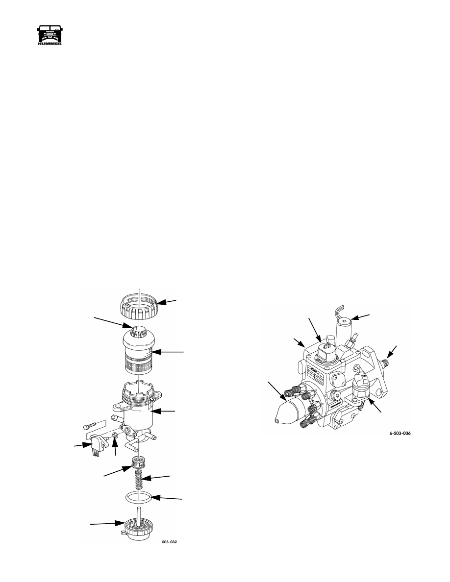
Fuel Filter-Water Separator
The filter-water separator is located at the driver side of the en-
gine compartment firewall (Figure 3-4). It performs five func-
tions which are:
• Fuel filtering (2-stage)
• Water separation
• Water detection
• Water drain
• Fuel heater
Fuel filtering and water separation is through a 2-stage, re-
placeable filter element. The filter second stage causes water to
separate from the fuel in the form of droplets. These droplets
are collected in a reservoir at the bottom of the filter element
housing. Water is then drained off through a drain valve and
hose. The drain valve is located in the driver side wheel well.
Water detection and fuel heating are controlled by sensors in
the filter housing. Water build-up causes the water sensor to
activate the instrument panel “drain filter” warning light. Fuel
heating occurs during cold ambient temperatures. It is con-
trolled by a sensor in the fuel inlet port that monitors incoming
fuel temperature. When temperature falls to a point where wax
build-up could occur, the sensor activates the heat element
within the filter housing. The heater will continue to operate
until incoming fuel temperature is at or above 46° F (8° C).
Figure 3-4: Fuel Filter Breakdown
Electronic Injection Pump
The turbo diesel injection pump (Figure 3-5) is controlled by
the powertrain control module based on inputs from the elec-
tronic accelerator pedal and various engine sensors.
The drive mechanism for the pump consists of a drive gear on
the camshaft, and a driven gear on the pump. The pump is op-
erated at camshaft speed in the opposite direction of rotation.
A rotary type pump mechanism pressurizes fuel to the injec-
tors. Pressure at the injector nozzles is approximately 2000 psi
(138 bar). Residual pressure in the injector lines is maintained
at 500 psi (3447 kPa) during operation.
Fuel distribution to individual nozzles occurs at the pump head
and rotor assembly and is activated by the fuel solenoid driver.
High strength, plated steel lines are used to connect each injec-
tor to the pump.
The powertrain control module controls injection timing and
fuel mixture according to input signals from various sensors.
A crankshaft position sensor and optical sensors are used to
provide engine and injection pump position and speed signals.
These signals are transmitted to the PCM and used as reference
for fuel flow and timing.
The injection pump is equipped with a shut off solenoid con-
trolled by the PCM. The purpose of the solenoid, is to close and
stop fuel flow within the pump. This occurs when the ignition
switch is moved to the “Off” position. At this point, loss of PCM
hold-open voltage de-energizes the solenoid causing it to close.
Figure 3-5: Electronic Fuel Injection Pump
AIR BLEED
VALVE
RETAINING
NUT
FILTER
HOUSING
SPRING
SEAL
HEATER
SCREEN
O-RING
SENSOR
ELEMENT
SOLENOID
DRIVER
FUEL
SOLENOID
PUMP
SHAFT
SHUT-OFF
SOLENOID
OPTICAL/FUEL
TEMPERATURE
SENSOR
INJECTION TIMING
STEPPER MOTOR
3-4
Fuel, Emissions, and Exhaust
_____________________________________________
®
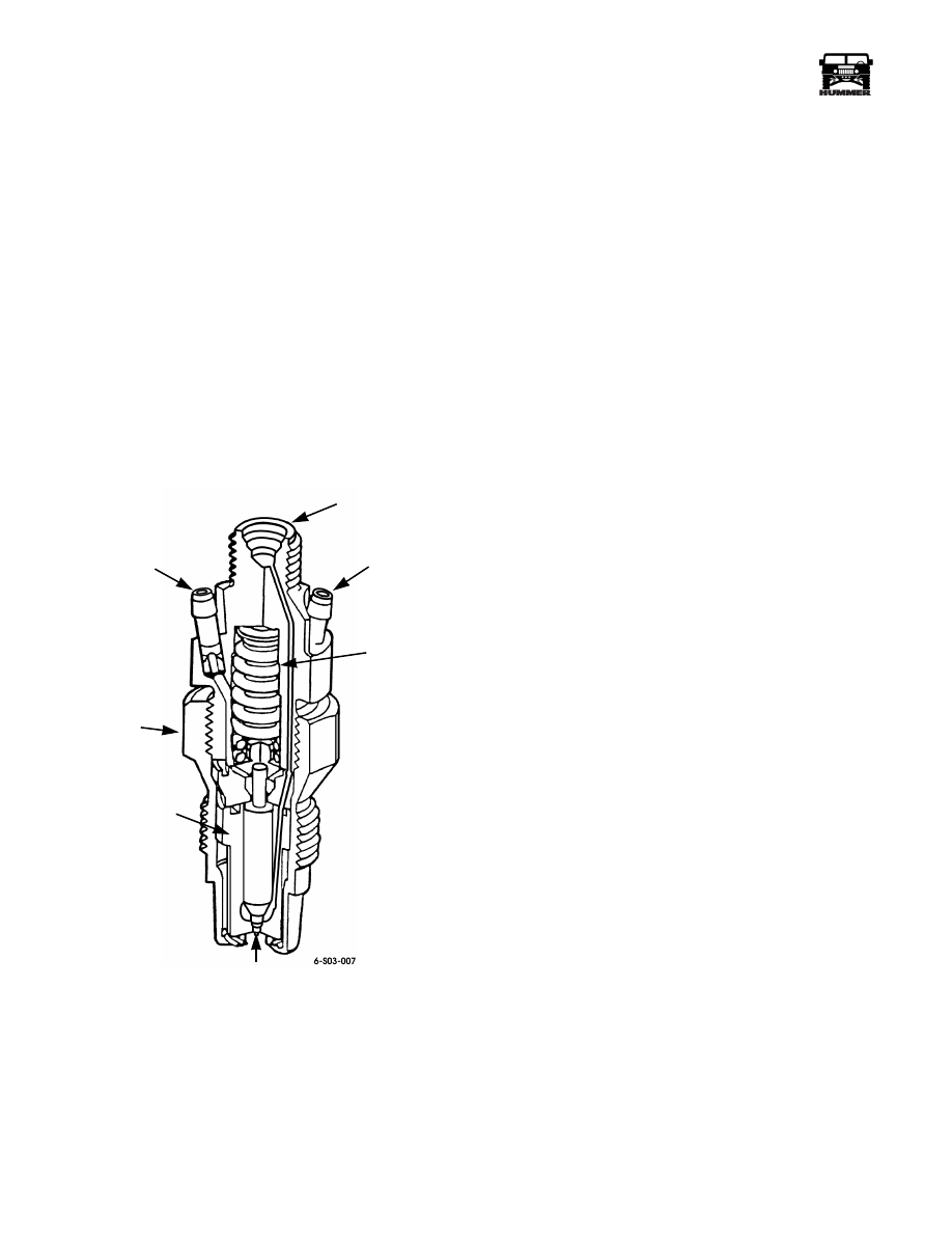
Fuel Injectors
An identical fuel injector nozzle is used for each cylinder. The
nozzle is threaded into the cylinder head and positioned so the
injector nozzle extends into the combustion prechamber.
The injectors are a spring loaded, valve and pintle design
(Figure 3-6). The pintle forms the injector nozzle and the valve
seats in the nozzle tip opening.
Fuel is supplied to each nozzle and in the necessary sequence,
by the fuel injection pump. The high pressure fuel pulse over-
comes spring pressure lifting the valve off its seat. Pressurized
fuel then enters the prechamber through the nozzle in the form
of a highly atomized spray.
A small amount of fuel travels around the nozzle and valve for lu-
brication purposes. This fuel cycles back to the fuel return system
through the fuel return ports at the upper end of each nozzle.
The fuel injection nozzles are not repairable and are serviced
only as an assembly. However, they may be cleaned to remove
contamination.
Figure 3-6: Fuel Injector Components
Fuel Tanks, Lines, and Valves
The main and auxiliary fuel tanks are made of high density
polyethylene. Auxiliary fuel tank capacity is 17 gallons (64.3
liters). Main tank capacity is 25 gallons (94.6 liters).
Quick connect fittings are used at most of the fuel line connec-
tion points.
Fuel level transmitters for main and auxiliary tanks are
mounted within the tanks. A selector valve, mounted on the
passenger side of the frame, controls tank flow and selection.
A check valve is used in the supply and return lines to prevent
backflow. Vent lines are used at both tanks to avoid internal
pressure buildup.
Fuel return lines are used to send unused fuel from the nozzles
and the injection pump back to the fuel tanks.
Glow Plugs
The diesel engine glow plugs are threaded into the cylinder
head and extend into the combustion prechamber. The purpose
of the plugs is to heat air entering the combustion chambers to
help start the combustion process when the engine is cold.
The glow plugs are used as an aid to starting; especially when
ambient temperatures are low. The plugs are cycled on/off for
short time periods prior to engine cranking and during initial
start-up. The plugs are not on continuously, as plug damage
can occur after 6-7 seconds.
Turbo diesel engines use a glow plug relay that is controlled by
the PCM based on inputs from engine temperature sensors.
The glow plugs will cycle after the engine has started to main-
tain good combustion.
Electronic Accelerator Pedal
Turbo diesel models are equipped with an electronic accelera-
tor pedal assembly (Figure 3-7). The assembly consists of a
pedal and arm, mounting bracket, and potentiometer module.
The pedal assembly mounts in a conventional location.
The pedal potentiometer module contains three potentiometers
that send varying voltage signals to the PCM. By comparing
the different voltage signals against a standard, the PCM can
determine fuel delivery rate based on accelerator pedal posi-
tion.
A “check throttle” warning light is used to alert the driver of a
problem with the pedal assembly.
Some faults in the pedal potentiometer module or related wir-
ing will trigger the check throttle warning light. The light is lo-
cated in the status center. Some faults will cause loss of cruise
control only and multiple faults in the APP circuit can result in
decreased performance or engine idle only.
FUEL
RETURN
PORT
INJECTOR
BODY
NOZZLE
PINTLE
VALVE
SPRING
FUEL
RETURN
PORT
FUEL
INLET
PORT
Нет комментариевНе стесняйтесь поделиться с нами вашим ценным мнением.
Текст