Hummer H1 (2002+). Manual — part 186
_____________________
Heating/Ventilation/Air Conditioning (HVAC) 11-23
®
05745159
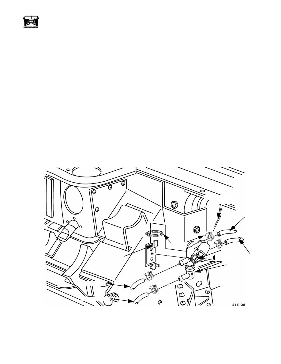
WATER CONTROL VALVE REPLACEMENT
Removal
1.
Place a drain container under the vehicle directly below
the control valve (Figure 11-19).
NOTE: Use extreme caution when working on a hot engine.
Let the engine cool down before proceeding.
2.
Relieve pressure from cooling system by loosening
coolant pressure cap.
3.
Remove the air intake hoses.
4.
Disconnect the vacuum hose from the control valve
diaphragm.
5.
Clamp control valve hoses with heater hose clamp pliers
or equivalent tool.
6.
Remove hoses from valve.
7.
Remove clamp and valve from mounting bracket.
Installation
CAUTION: Do not overtighten the clamp that secures the con-
trol valve to the mounting bracket. Overtightening the clamp
can deform the valve housing and cause binding. After tighten-
ing, push the plunger in and out of the vacuum diaphragm to
ensure the valve is moving freely.
1.
Gently secure control valve to mounting bracket with
clamp (Figure 11-19).
2.
Secure hoses to valve with clamps.
3.
Release and remove hose clamp pliers or equivalent tools
from valve hoses.
4.
Connect the valve vacuum hose (Figure 11-19).
5.
Check the coolant level and add coolant if necessary.
6.
Tighten coolant pressure cap.
7.
Check the valve for proper operation and leaks.
Figure 11-19: Water Control Valve Installation
TO HEATER
FROM HEATER
TO ENGINE
FROM ENGINE
FROM VACUUM
SOLENOID
WATER CONTROL
VALVE
MOUNTING
BRACKET
CLAMP
PLUNGER

11-24
Heating/Ventilation/Air Conditioning (HVAC)
______________________
®
MAIN A/C - HEAT UNIT COWL INSULATION
REPLACEMENT
Removal
1.
Remove air intake weathercap (Section 3).
2.
Remove air cleaner assembly shield.
3.
Remove vent line from air cleaner assembly.
4.
Remove air cleaner assembly and air induction tube.
5.
Loosen and remove two clamps and move surge tank out
of the way.
6.
Remove drain tube.
7.
Remove trim screws, as necessary, from insulation on air
intake housing (Figure 11-20).
8.
Remove screws and washers, as necessary, from insulation
on upper cowl.
9.
Remove bolts, nuts, and fasteners, as necessary, from
insulation on front of cowl.
10. Remove three nuts and washers from insulation on main
A/C - heat unit mounting studs.
11. Remove cowl insulation.
Figure 11-20: Cowl Insulation Mounting
Installation
1.
Position cowl insulation so that flap side is inserted under
surge tank bracket (Figure 11-20).
2.
Install three nuts and washers to secure insulation to main
A/C - heat unit mounting studs.
3.
Install bolts, nuts, and retainers as necessary to secure
insulation to front of cowl.
4.
Install screws and washers as necessary to secure
insulation to upper cowl.
5.
Install trim screws as necessary to secure insulation to air
intake housing.
6.
Install drain tube.
7.
Install two surge tank screw clamps to secure surge tank.
8.
Install air cleaner assembly and air induction tube (Section
3).
9.
Install air cleaner assembly vent line.
10. Install air cleaner assembly shield.
11. Install air intake weathercap.
DRAIN TUBE REPLACEMENT
Removal
Remove drain tube from main A/C - heat unit inner cowl area
by pulling straight out. If drain tube grommet pulled out with
drain tube, it will need to be reinstalled. It may be necessary to
loosen drain tube from main A/C - heat unit drain outlet.
Installation
Install drain tube and grommet, if removed, to drain tube outlet
on main A/C - heat unit (Figure 11-21). Ensure drain tube is at-
tached to main A/C - heat unit drain outlet.
Figure 11-21: Drain Tube Replacement
TRIM SCREWS
SEAL RETAINER
OVER INSULATION
FRONT
FASTENERS
AIR INTAKE
HOUSING
UPPER
COWL
FLAP
COWL
INSULATION
BLOWER MOTOR
RESISTOR
GROMMET
DRAIN TUBE
_____________________
Heating/Ventilation/Air Conditioning (HVAC) 11-25
®
05745159
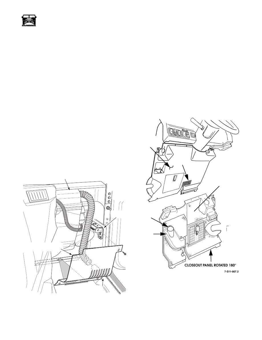
AIR CONDITIONING/HEATER DUCT
REPLACEMENT
Passenger Floor Duct
Removal
1.
Remove right side crash pad (Section 10).
2.
Remove screw securing passenger side closeout panel to
upper closeout panel bracket (Figure 11-22).
3.
Lower panel down, and pull rearward to remove from
lower bracket (Figure 11-22).
4.
Remove screw securing duct hose to closeout panel
(Figure 11-22).
5.
Remove screw securing duct hose to the drivers floor duct
assembly (Figure 11-22).
6.
Remove duct hose
Installation
1.
Route new duct hose from drivers floor duct to closeout
panel along right side of the main HVAC unit.
2.
Secure the duct hose at both ends with a trim screw.
3.
Put the bottom of the passenger side closeout panel into
the lower bracket., raise the rear to the upper mount
bracket and secure with a trim screw.
4.
Install crash pad.
Figure 11-22: Passenger Floor Duct
Driver Floor Duct
The driver floor vent and floor duct are both integrated as part
of the closeout panel assembly. Failure of either component
constitutes closeout panel assembly replacement.
Removal
1.
Remove screws and closeout panel from instrument panel.
2.
Remove duct hose from driver floor duct on back side of
closeout panel.
Installation
1.
Attach duct hose to driver floor duct on back side of close-
out panel.
2.
Secure closeout panel to I. P. with screws.
Figure 11-23: Driver floor Duct Appearance
7-S11-074
VENT
PASSENGER FLOOR
DRIVERS FLOOR DUCT
PASSENGER SIDE
CLOSEOUT PANEL
UPPER
BRACKET
CLOSEOUT
PANEL
DUCT
HOSE
CONNECTS
HERE
DRIVER
FLOOR
DUCT
DRIVER
FLOOR
VENT
CLOSEOUT
PANEL
(VIEWED
FROM BEHIND)
~
11-26
Heating/Ventilation/Air Conditioning (HVAC)
______________________
®
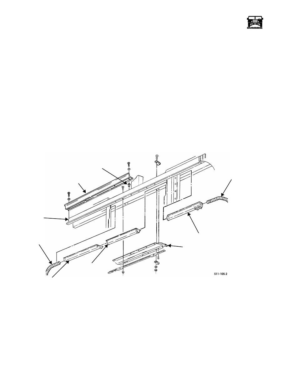
DEFROST DUCT AND WINDSHIELD NOZZLES
REPLACEMENT
Center Defrost Duct
Removal
1.
Remove right side crash pad (Section 10).
2.
Remove front console (Section 10).
3.
Remove engine cover (Section 10).
4.
Remove twelve screws, nuts, washers, and closeout panel
from A-beam (Figure 11-24).
5.
Remove eight screws, washers, and driver’s and pas-
senger’s lower windshield retainers from A-beam.
NOTE: Plusnuts must be drilled out in order to remove ducts.
New plusnuts are installed in the same holes.
6.
Remove center defrost duct from A-beam.
Installation
1.
Install center windshield defrost duct into A-beam
(Figure 11-24). Align both ends with adjacent duct and
insuring a leak-free overlap joint.
NOTE: Apply Silaprene Sealant 05593929 in a continuous
bead around the new plusnuts making sure to cover both the
edge of the plusnut and the vehicle body. This will provide bet-
ter sealing.
2.
Install new plusnuts into A-beam.
3.
Install driver’s and passenger’s lower windshield retainers
on A-beam with eight screws and washers.
4.
Secure closeout panel to A-beam with twelve screws,
plusnuts, and washers.
5.
Install engine cover (Section 10).
6.
Install front console (Section 10).
7.
Check operation of windshield defrosters.
8.
Install right side crash pad (Section 10).
Figure 11-24: Windshield Defrost Ducts and Nozzles
SIDE WINDOW
DEMISTER VENT HOSE
DRIVER WINDSHIELD
DEFROST NOZZLE
CENTER WINDSHIELD
DEFROST DUCT
PASSENGER WINDSHIELD
DEFROST NOZZLE
SIDE WINDOW
DEMISTER VENT HOSE
A-BEAM
DRIVER LOWER
WINDSHIELD RETAINER
CLOSEOUT PANEL
PLUSNUT
Нет комментариевНе стесняйтесь поделиться с нами вашим ценным мнением.
Текст